I recently created a kit that lets you convert the D700 to a GPS-in-head design like the later TM-D710GA model. When I went to apply the kit to my oldest D700 sample I encountered a problem: the display would just strobe when powering on. The radio was clearly in a boot loop. If I unplugged the GPS device inside the head, it would power on normally. If I set the backlight dimmer to off (or almost-off) it would power up properly. None of the other D700s I had did this.
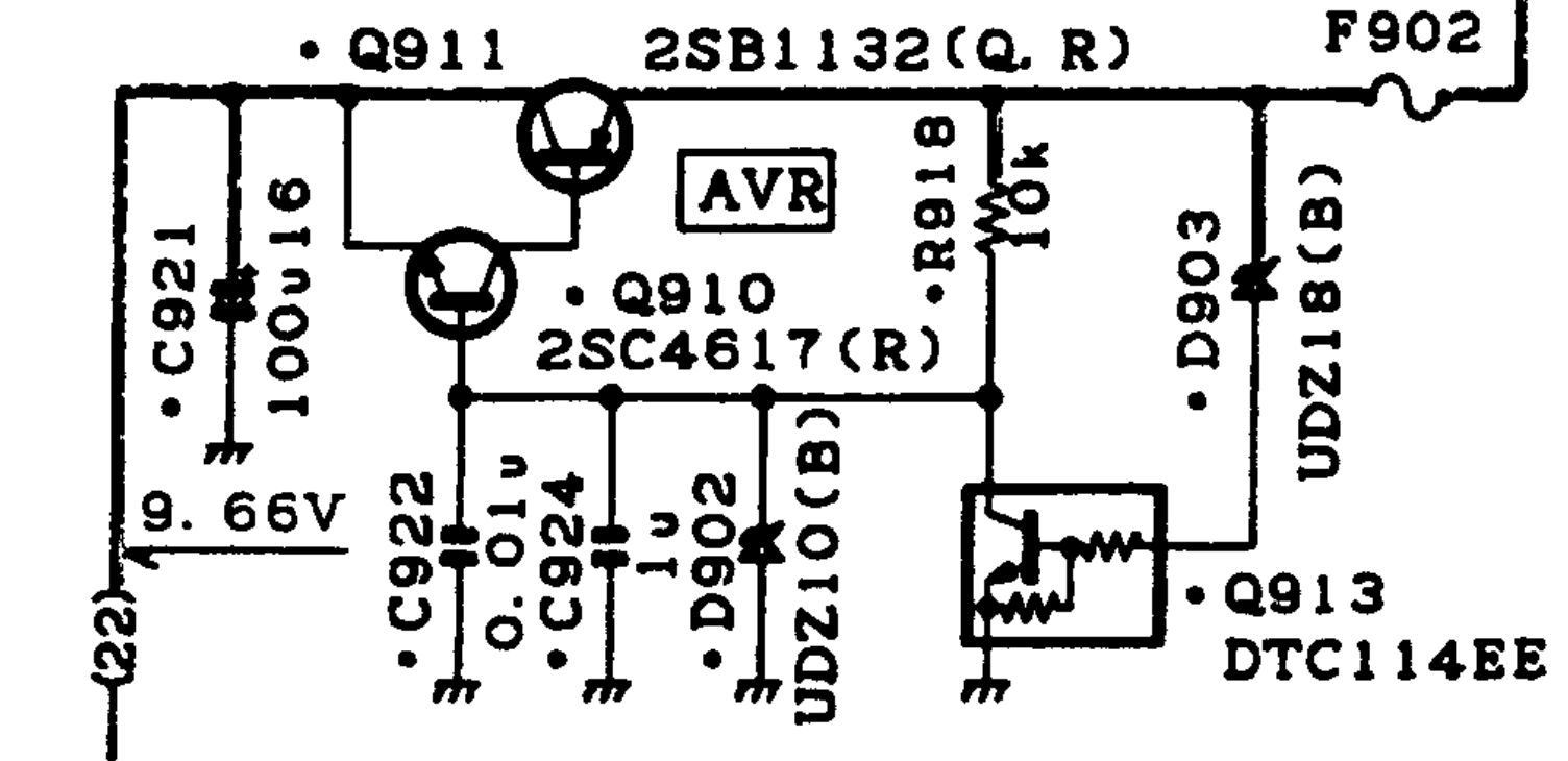
I measured the voltage of the power supply (signal PB on the schematic) to the head at just over 6V when powered on, even without the GPS. I knew this was wrong because I had investigated the power supply for the head to make sure my GPS conversion would have headroom to power the device. It should have been about 9.6V. With the GPS plugged in, it was dropping to just above 3V. Here’s the AVR circuit for the display head from the schematic:
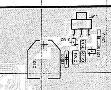
Q911 does the heavy lifting here: a 1A-rated PNP transistor as a voltage follower, controlled by the UDZ10 10V zener and the small NPN transistor Q910. When I checked my Q911 I found it shorted in every direction except collector to emitter. Thus, I think the very small transistor Q910 was all that was powering the head, and it’s only supposed to be a reference for the bigger Q911 which explains why the 50mA GPS load dragged it down too low. After coming to this realization, I also realized that this D700 had a dimmer backlight than all my others.
The 2SB1132 part in the schematic is long since obsolete, but I found a 2SAR293P5T100 pin-compatible replacement that was close enough. Q911 is on the bottom side of the board, so you have to unsolder the RF connector and remove all the screws to get it out and flip it over. Here’s the AVR section in the service manual view:
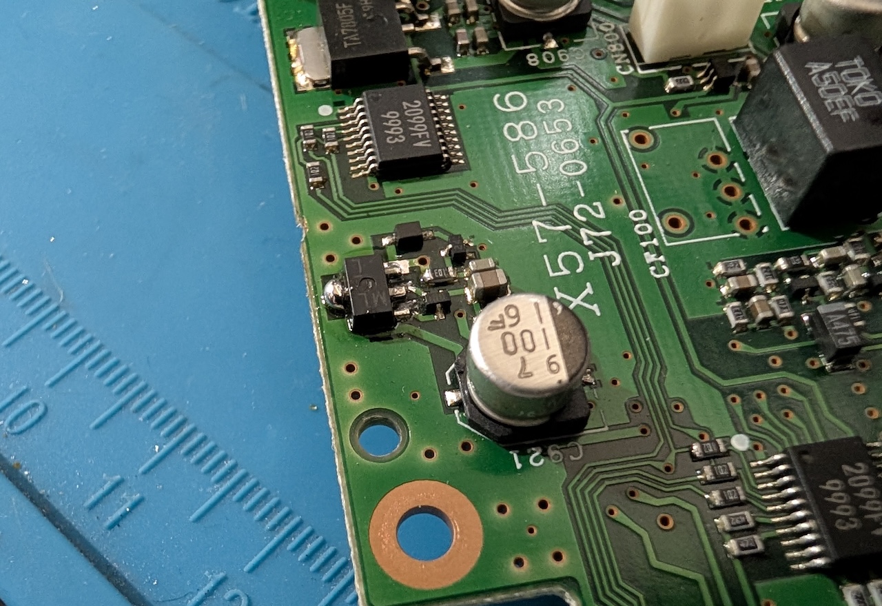
Here is the actual picture of the board, with the device replaced:
After this, the PB line of the head cable shows 9.6V on the dot, and has no problem powering the internal GPS now. I’m not sure when my transistor died, but I might not have noticed until the little reference transistor finally burned out. It would be a much more challenging repair, as tiny as it is. I found other reports of people with burned out display power supplies due to crushed/shorted control cables. Hopefully this helps someone in case they experience a sporadic or traumatic failure.
I have a couple of Kenwood TM-D700 radios that I like. They are really solid, and for the most part, very good for their integrated APRS capabilities. In the old days when you had to connect a GPS to the radio to get it to beacon, I actually preferred the D700 because the GPS connected to the radio itself, instead of the head like the D710. I always thought that was a really unfortunate design point of the later radio – having to route another cable to the head. When the D710GA came out, that became moot of course, as building the GPS into the head unit itself made it mostly a non-issue.
There are a couple other drawbacks to the D700, like lack of smart beaconing and some annoying rules that require you to run APRS on the left side of the radio in order to tune anything on the right side. But aside from that, they’re nice. I have made a couple of attempts to modernize my D700s in the last, like by hiding a bluetooth serial module in the radio itself. That’s neat and handy, but only useful for a few circumstances.
Recently I had an idea to also integrate a GPS module into the plastic nose as well. I did cram one in there, but it’s becoming a mess (with the bluetooth module as well) and the size of GPS antenna I was able to get in there left me with really sub-par performance. That, and a lot of people mount the radio body in a trunk or under a seat, which makes a receiver in the radio itself less than ideal.
After doing all that work and being underwhelmed, I thought: what if I were to integrate a GPS module in the head unit and plumb it back through to the radio? Putting the GPS receiver in the head was a very nice benefit of the D710GA, since most people have the head up front, usually in view of multiple windows, etc. Doing something similar for the D700 would be nice.
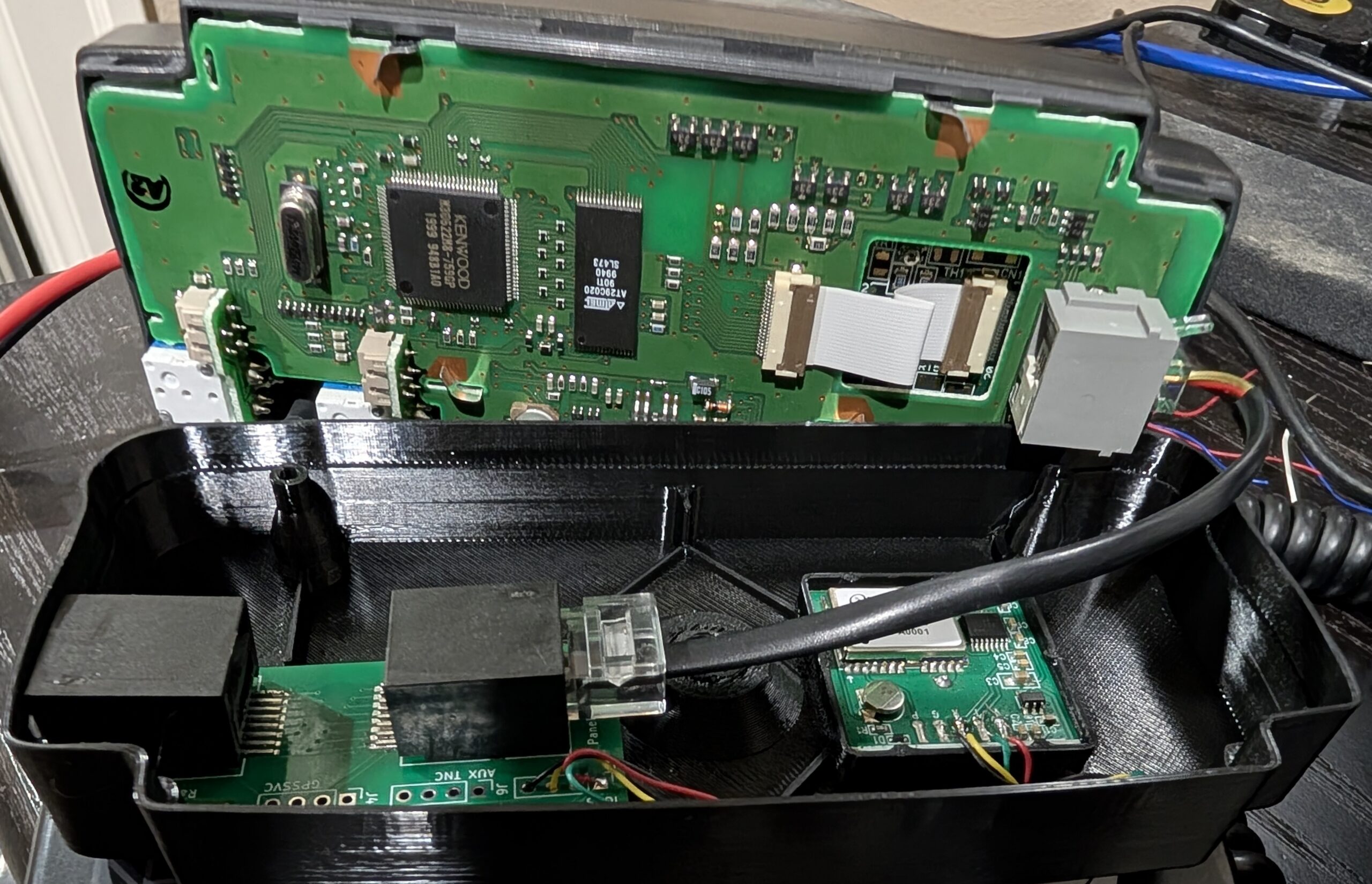
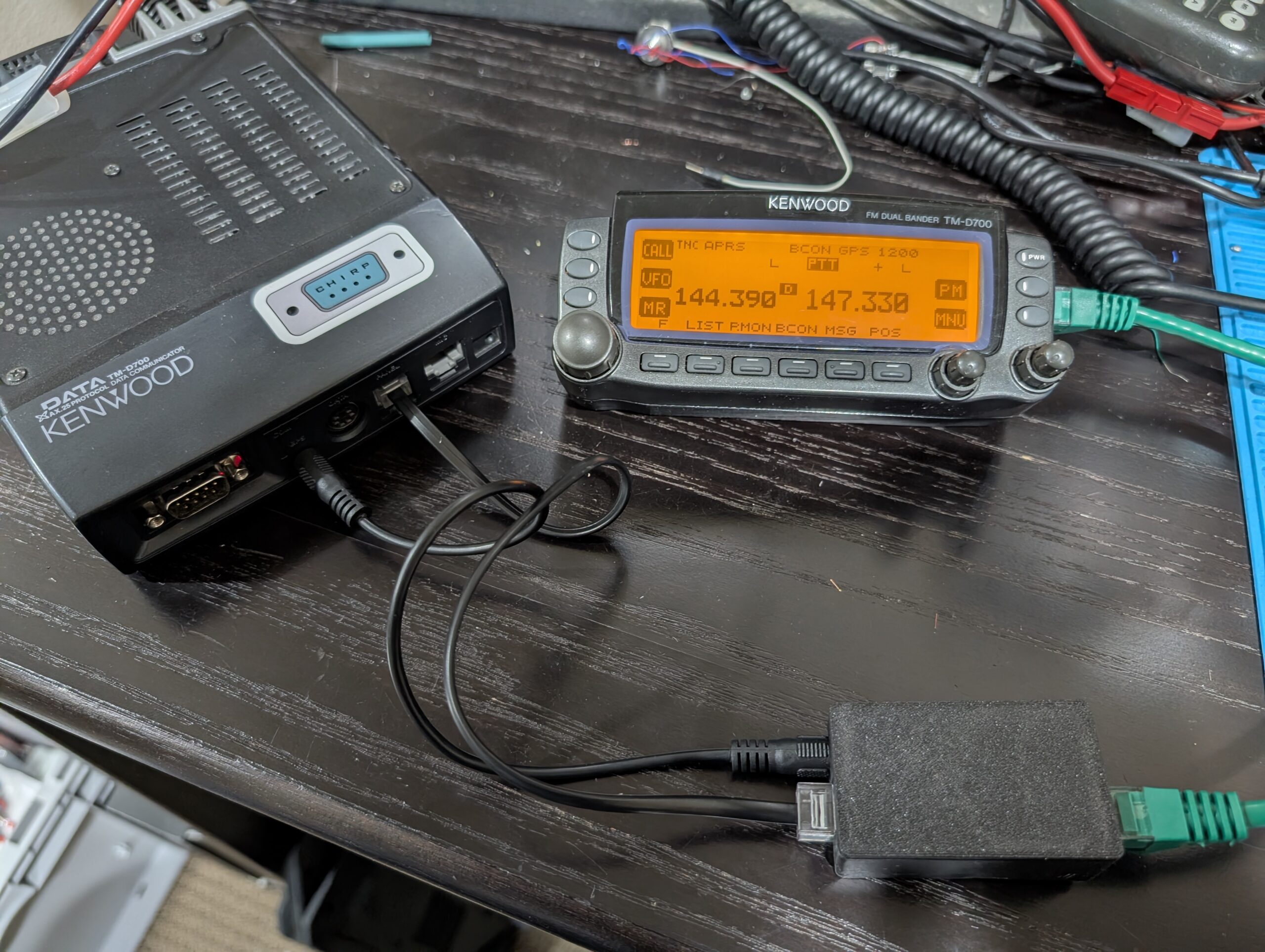
So, I present to you…the D700GA conversion kit. This is a replacement back cover for the control head that houses a GPS receiver and an interface board. The interface board squashes the four usual pins of the control head interface into an 8P8C modular plug (like the D710 uses), along with GPS data lines. Then, another board on the other end of a standard ethernet cable splits the two back out into the RJ11 head cable and 2.5mm GPS data cable. The replacement back cover hides a jumper to the 4P4C original head connector on the left and presents the 8P8C on the right, fully contained within.
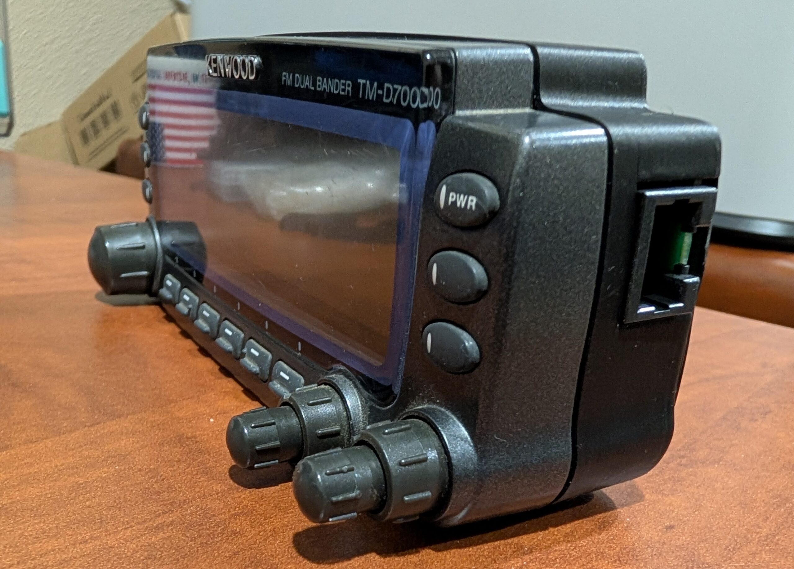
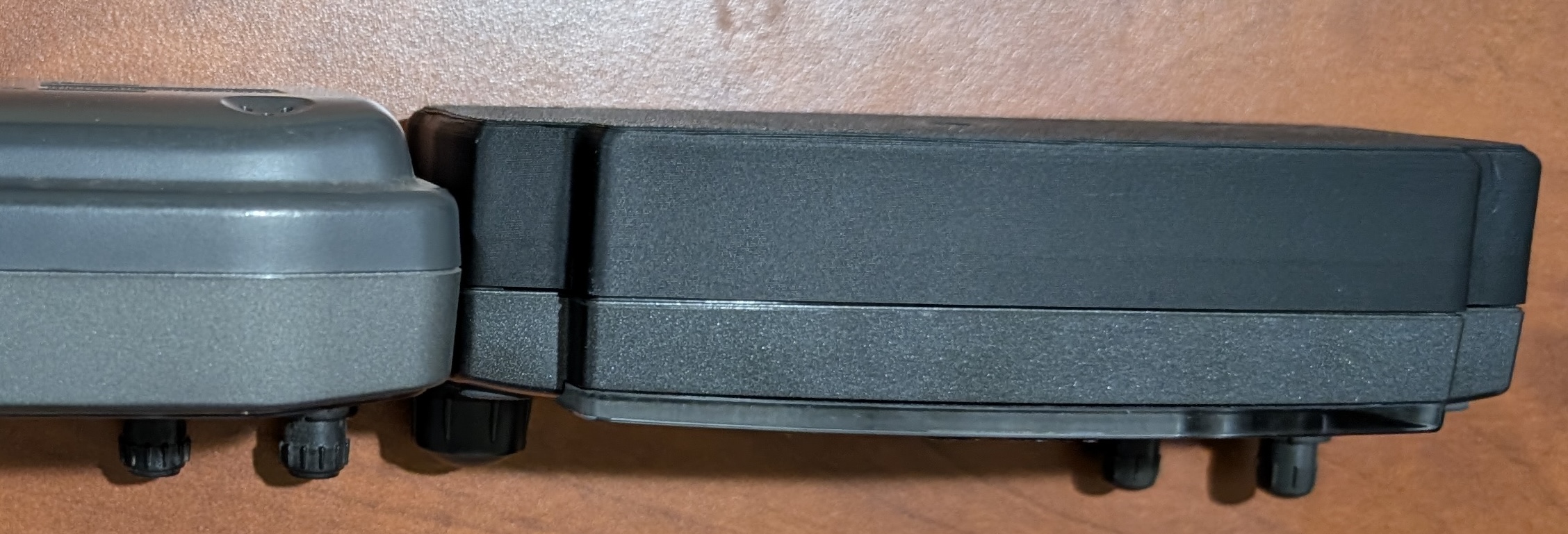
The result is a D700A radio that behaves like a D710GA – you just turn it on, it has GPS and can beacon. The new cover makes the head significantly thicker, but it’s actually similar to the thickness of a D710.
The GPS has a much larger antenna than the one in the D710GA and can maintain a much better fix in suboptimal conditions. It also receives GLONASS and GALILEO in addition to GPS for better performance. Instead of replicating the weird slot mount of the original head, I just integrated 1/4-20 hardware into the back cover for easy interfacing with many other mounting solutions.
And like the D710, this now allows the use of any off-the-shelf straight-through ethernet cable as a head separation path – much easier to source than the RJ11-to-RJ9 cable that the naked D700 requires.
As I recently wrote, we encountered a “P0757-2-3 SOLENOID” code in our 2012 Jeep Wrangler Rubicon Unlimited (JK) on a trip. This came with a refusal to shift out of 2nd or 3rd gear, and eventually a check engine light. The service data instructions say to check all the wires between the TCM and the transmission for open or short, as well as the resistance of the solenoid coil in question. If all of those check out good (which they did), then replace the TCM. I did that and the problem returned.
As I mentioned before, the problem seemed to originally manifest when I hit a bump in the road. While testing the “new” TCM, the same thing happened: the error state occurred right after a bump in the road. Pulling over and resetting codes fixed the problem, and then it manifested again on the next bump. While this could be an intermittent fault in the solenoid coil itself, I was starting to suspect the wiring again.
Even though I tried testing for open and short-to-another-circuit conditions on the wiring harness while jiggling the wires, I was unable to find any sort of problem. Service data does not provide a very clear routing of the wiring harness, and zooming in the grainy picture seemed to indicate that the harness left the kick panel under the steering wheel (where the TCM is) and punched through the transmission tunnel on top of the transmission itself. However, that’s not the case – it goes into the main engine harness, through the firewall into the engine bay, and then down alongside the bell housing. Checking for issues in this area, I found the probable culprit.
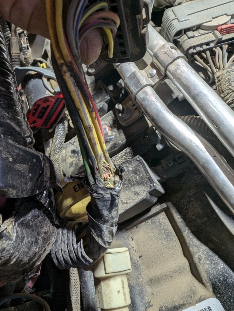
The C100/C106 connector normally resides right next to the battery in the stock location and has the transmission control/monitor wires in it. Since I had installed the MORE dual battery tray years ago, that harness no longer had a good place to sit and was sort of laying next to the battery. Over time, the factory plastic loom has disintegrated from the heat, exposing the wires directly and also allowing the harness to slip down between the battery tray and the engine head. It was here I caught a clear view of the problem: the wires had been pinched and their insulation destroyed.
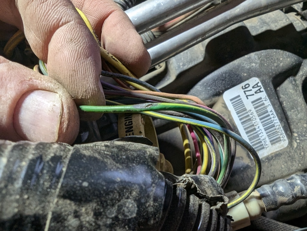
One of the conditions for setting the P0757 code is “shorted to another circuit” which really means “shorted to something other than ground”. The big yellow wire in the front of the above frayed bundle is a 12AWG ignition power circuit. In addition, several others had bare copper exposed, including the LightGreen/Yellow(stripe) wire, which is the 2-3 solenoid circuit:
It seems clear to me that being pinched where it was, the wires were not quite in contact with each other, but close. As soon as I hit a good enough bump, the engine would rock against the bundle and squeeze the wires together, causing the fault condition.
I separated the wiring harness a little further so I could re-route it, repaired all the wires that had been exposed, wrapped them in fresh loom, and bundled everything back up. It can now be secured to the battery tray well above the valve cover, out of harm’s way so hopefully that won’t happen again. Obviously my fault for not securing this well enough when the original mod was made, but at the time the loom was healthy and it seemed to stay well out of the way on its own.
We recently had something weird happen with our 2012 Jeep Wrangler Rubicon (JK), and I figured I better document the symptom and fix for posterity. We have the WA580/NAG1 5-speed auto transmission and the 3.6L Pentastar engine.
The first symptom may be unrelated, but it seems like too much of a coincidence to omit. We started the vehicle to drive home and noticed that the front power windows were entirely non-responsive. The rears worked fine, but the fronts were totally dead, like a fuse was out. As we drove, we also noticed that the transmission wasn’t shifting out of 2nd or 3rd gear (it was hard to tell without a reader) and it would not respond to an attempt to manually shift. We pulled over, power cycled the car, and everything seemed back to normal.
As we were driving home we suddenly got a check engine light and the instrument cluster went dim (as it does). This seemed to correlate to a moderate bump in the road, but it’s hard to say for sure. We again noted that the transmission seemed stuck in 2nd or 3rd gear (i.e. limp mode).
Once we got it into the garage, I checked for trouble codes and found a P0757 which identifies in a generic reader as “Shift Solenoid ‘B’ Stuck On”. However, the Jeep-specific code reads as “P0757-2-3 SOLENOID”. Basically, something wrong with the transmission solenoid responsible for triggering the shift from 2nd gear to 3rd. I followed the service data procedure for diagnosis, which involved checking the wiring between the Transmission Control Module (TCM) and the solenoid pack in the transmission, as well as checking the resistance of the 2-3 solenoid coil. That all checked out (5 ohms exactly for the coil). Service data called for replacing the TCM under those circumstances because the only thing left is the output driver in the TCM that controls that solenoid.
So, I ordered a new (to me) TCM (part number 05150729AE) from eBay and put it in. Service data says that replacing the TCM requires resetting the adaptive learning settings and re-training. I reset those (using JScan) and went for a drive. Almost immediately, it was clear that the transmission still wasn’t shifting. No check engine light (yet) but it was still in limp mode. I drove easy for a while until the transmission temperature got above the required level for the learning to start, in case it remained in limp mode until that point and then started working, but it did not.
In a parking lot I pulled codes from the TCM and found a new one: P0731 which is “P0731-GEAR RATIO ERROR IN 1ST”. From a quick google, it seemed that most people get this when they re-gear and don’t update the gear ratio in the ECU. I thought maybe this new TCM doesn’t know our gear ratio, having just been transplanted into a different vehicle (with a non-standard ratio), and that it was thus unhappy and the error made sense.
Poking around in JScan, I saw that the gear ratio in the ECU was still set properly for our setup (4.56) and didn’t see any way to tell the TCM about the ratio. I figured maybe I’d try re-programming the ratio to the same thing, which I did. Once finished, JScan said that I needed to go run the “Initialize EGS” procedure to “transfer powertrain information to the TCM”. That seemed promising, in that it fit with my guess about needing this transplanted TCM to learn the attributes of the new vehicle.
I ran that procedure, which required me to cycle the ignition a couple times. After that, I started up and immediately had 1st gear and proper shifting afterwards. Drove around a bit and then back home without throwing any more codes or exhibiting any weird behavior.
Most people will recognize CHIRP as a desktop application, which it is. However, one of the early design points for the architecture was a clear separation between the UI and the driver model. That provides a mostly clean abstraction between the task of communicating and interpreting the memory of the radio and the presentation or user interaction. While the chirp python module is not a stable library, it’s pretty internally-consistent and doesn’t change much over time. What that means is that it’s also possible to re-use the driver code in other tooling for specific purposes.
I recently got an SPE Expert 1.3K-FA linear amplifier with the integrated antenna tuner. It’s a really nice piece of gear, and it’s very well thought-out. The ATU works differently than I was expecting though, in that you pre-tune it for basically everywhere you want to operate and it automatically tracks as the frequency changes via CAT. That means it’s constantly adjusting the ATU as you dial around, which is great, but it means that you need to have done that pre-tuning ahead of time.
In order to do that, the manual gives you a large table of “sub-band center frequencies” across all the supported bands. If you make changes to your antenna, or operate on a temporary antenna, you need to re-tune every single one of them. The OEM process consists of these steps:
Look up the next frequency in the list
Dial the radio to that frequency
Set the radio to CW or RTTY (which my radio is never in)
Press the tune button on the amp
Key the radio until the tuner finishes
Goto step 1 (until you’ve done them all)
For me, step 2 takes the most time, either typing each frequency in on the direct-entry keypad or using the dial. Multiply that procedure by the 153 center frequencies (if you do all the bands) and you can see why it takes some time.
My thought was that I can/should automate that using the infrastructure in CHIRP. So I did, and what I came up with works really nice with my setup to make a full re-tune much quicker. The tool’s fully-automated workflow looks like this:
Command the radio to the next frequency in the list, RTTY mode
Monitor the output to see that you key the radio, and when you un-key:
Switches to CW mode and sends your callsign for ID (if supported), then loops back to #1
The only the thing user has to do is hit the tune button on the amp and transmit when prompted, over and over again. It’s much faster and less work. Here’s a sample interaction:
It’s tempting to use the USB interface on the amplifier itself to fully automate this process, which is very doable. However, it’s probably most prudent to require some user interaction in order to listen for a clear frequency before tuning and, of course, monitor for problems (like a failure to achieve a suitable match, etc).
I tested this on an IC-7610, IC-7300, and IC-7200. It’s certainly possible it will run with ease on other such models, but I don’t have them handy to test with. Since this uses a bunch of control frames that are not normally used (and tested) as part of CHIRP, it’s hard to say if they will all work with other models.
If you want to check it out you can see it here. It requires the chirp python module to be installed (or be locally resident). An all-in-one binary could be made.
The Kenwood TK-8180 is my go-to preferred radio for GMRS stuff. It is a rugged radio with an excellent remote-head kit, and a nice display. It’s generally pretty easy to find them in good condition on eBay, and accessories are plentiful and compatible with a long line of Kenwood radios.
The TK-8180 (and TK-7180 VHF radio) have an excellent expansion port in the back that uses a standard DB-25 female connector, which makes it super easy to interface with. In my Jeep, I mount the remote head high above the roll bars near the roof to keep it out of the way and the body of the radio under my seat. However, I don’t want to have the mic up there, with the cable drooping in my face. Luckily the expansion jack can take mic audio and PTT signals instead of the mic jack on the head.
Even though this is rather trivial, I’m documenting the connection here for my future self, and others, as I have seen people ask about this before. I’m using a KMC-35 mic, but this should work with most any Kenwood commercial mic (keypad mics that use the serial connection will not have DTMF functionality).
I used a simple surface-mount box meant for ethernet to provide a mic jack low on the center console. If you’re familiar with (and/or your surface-mount box is marked for) T568B ethernet wiring, I kept the wire colors consistent here to make it easier. I used the software to set AUXI/O7 (pin 12) to “External PTT (Voice)” and “Active Low”. If you choose a different pin for PTT, make sure to adjust accordingly in the table below.
RJ-45 Pin
DB-25 Pin
Signal
T568B Standard Color
1
W/Orange
2
Orange
3
6
Mic Audio
W/Green
4
25
Mic Gnd
Blue
5
12
PTT
W/Blue
6
7
Gnd
Green
7
14
SB (+12v)
W/Brown
8
Brown
The TK-8180 can also tolerate both mics being connected at the same time, and the radio will route audio from the proper one depending on which PTT is pressed. This is not important for my application, but may be for others.
I have a Kenwood TM-281 that I got second-hand from an unknown source, and have always programmed it by hand since it’s so simple. Recent efforts in the chirp py3 branch require a lot of re-testing of radios, so I decided to pull out my TM-281 for a quick verify. Come to find out, it was totally dead in terms of serial communications. Neither chirp nor Kenwood’s own program would talk to the radio, and a serial terminal confirmed no communication at all.
I whipped out the schematic and traced the two serial lines from the mic connector that are required to operate. The HOOK line is used as data RX for the radio, and has a zener diode (D902) between that line and ground, presumably to clamp RS-232 level voltage to the 5v it expects. I found this diode to be shorted, failing a diode direction test and registering about 4ohms to the chassis.
Since I’m using a proper 5v TTL cable, I decided to lift one side of the diode to break the short to see if that would allow communication. Luckily, it did and the radio immediately started responding to serial commands normally. Here’s a picture of the diode lifted:
Obviously the proper fix is to replace the zener with a suitable substitute, although it’s not clear to me what the right part is. The service manual shows it as “UDZW6.2(B) ZENER DIODE” which does not resolve to much for me. However, I suspect it’s just a 5V zener.
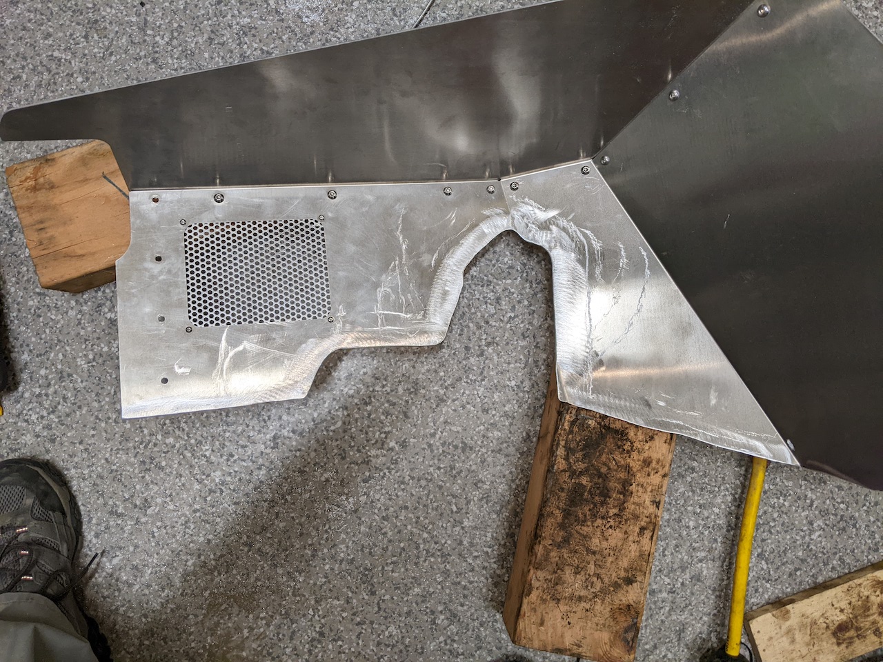
I recently installed GenRight regular aluminum front fenders on my TJ. It was my first time doing fenders and it turned out to be a lot more than I was planning for, so I thought I’d document some of my notes here for anyone else that might be wondering about the process. I’ll also include some thoughts on GenRight and the fenders in general.
First off, I called GenRight before I ordered, asking for the install instructions ahead of time. I hate when companies don’t just publish these on their site, both for pre-order information, but also because I want to maintain a PDF copy long-term and refer to that during install. They were super nice on the phone and assured me that the install was very easy if you also go with their inner fender liner (which I wanted anyway). They did email the instructions after the call, but they were the wrong ones (for the hi-fender instead of the regular). But, I figured they’d be pretty much the same, minus the cutting of the hood and ordered.
The shipment came super fast via FedEx, which was awesome. Seems like most places have a lead time measured in weeks. I was, however, not impressed that some of the pieces were missing instructions, and some had the wrong instructions included. I ended up getting all the right PDFs from them after a second call, including other things they had said would be included, like a template for trimming my existing sliders. The guy on the phone noted that “oh by the way, the instructions don’t mention that you need to find a new washer bottle because the old one won’t fit.” That was the first indication that the instructions were vastly under-documenting the process. I think that keeping the stock inner fenders would have been massively easier (although I’m glad I now have flat surfaces under the hood for mounting new things).
The other thing is, even after I got the right instructions from them, they clearly were written years ago and the actual products I received had been revised since then. I can guess at how stuff goes together as good as the next guy, but I assumed that for the price premium I’d be getting instructions that matched the stuff I ordered.
So, I’m disappointed in the instructions and lack of communication of all the details involved. Obviously I’m happy with the outcome and the quality of the actual product.
Install Notes
Don’t even bother trying to get the old fender off and the new fender on with the sliders in place. I did get one side off and did a little fitting of the new fender, but ultimately removed the sliders for most of the job. Mine are two-piece JCR sliders, so that was more work than otherwise. Also, plan to remove not only the battery tray, but also the mounting bracket (on both sides!) for initial fitment. In fact, plan to mount and un-mount pretty much everything a couple hundred times.
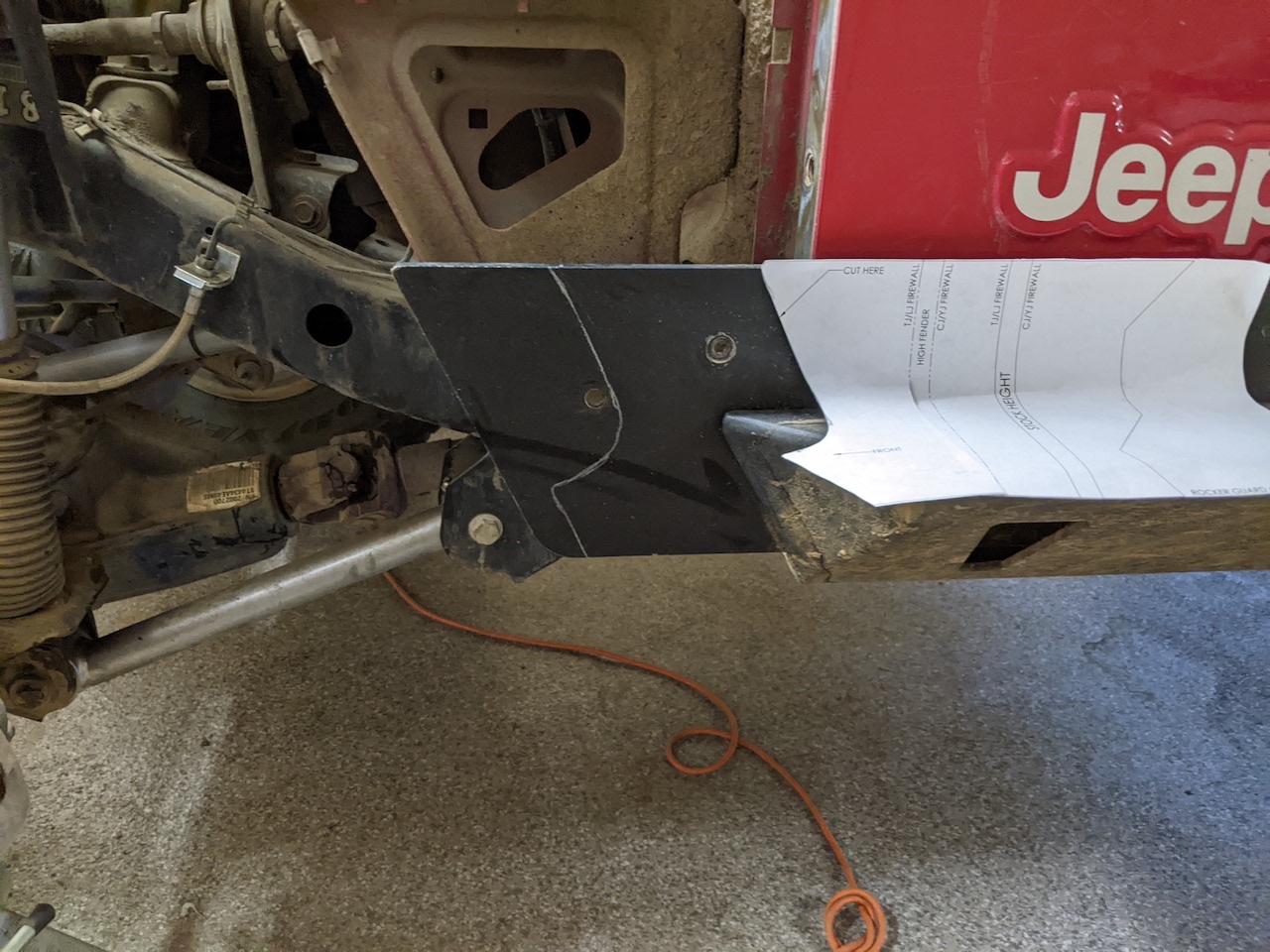
The template they gave me for trimming the sliders was helpful, but it wasn’t clear exactly where to line up the “TJ Firewall” line, since the firewall is a stamped piece of steel that isn’t remotely flat. I went conservative and ended up cutting multiple times for clearance. I used a plasma cutter with the slider on the vehicle and then traced that side to the other side when I had it right. My sliders had a bolt that went through the front fender, which was still in a good place to bolt through the GenRight fender, so I did that.
Cutting the sliders to fit around the fender tube
When fitting the fender, the front clip needs some coaxing to line up with the bolt holes. There is almost not enough clearance inside the front mounting area of the fender to even line up the bolts. I initially used a long philips screwdriver to move the front grille into place, but ended up boogering up threads. The proper procedure is to get the bolts on the front started and then move the body-side of the fender into place since you effectively have a big lever to work with at that point. Plan to use an open-ended wrench on the front bolts with 1/4 turns for ages to get them fully seated.
Pre-fitting the inner liner to mark before cutting
This was not described in the instructions, but the product page for the inner fenders mention they are “not trimmed for any specific suspension” and also “oversized for body lifts.” So I ended up cutting large chunks out of them to fit around the factory suspension mounts and to clear brake lines using a jigsaw. To do this, I first fitted the fender, jammed the inner fender into place underneath it until it mostly seats where it should, and traced the outline of what I needed to trim on the inner. After the first cut, it fits a lot better under there, but on both sides I still had to make a lot of adjustment cuts before everything cleared. I did all of this until I had it right before I did the pop rivets to permanently mount the inner to the fender.
The inner fender trimmed to clear the suspension mounts
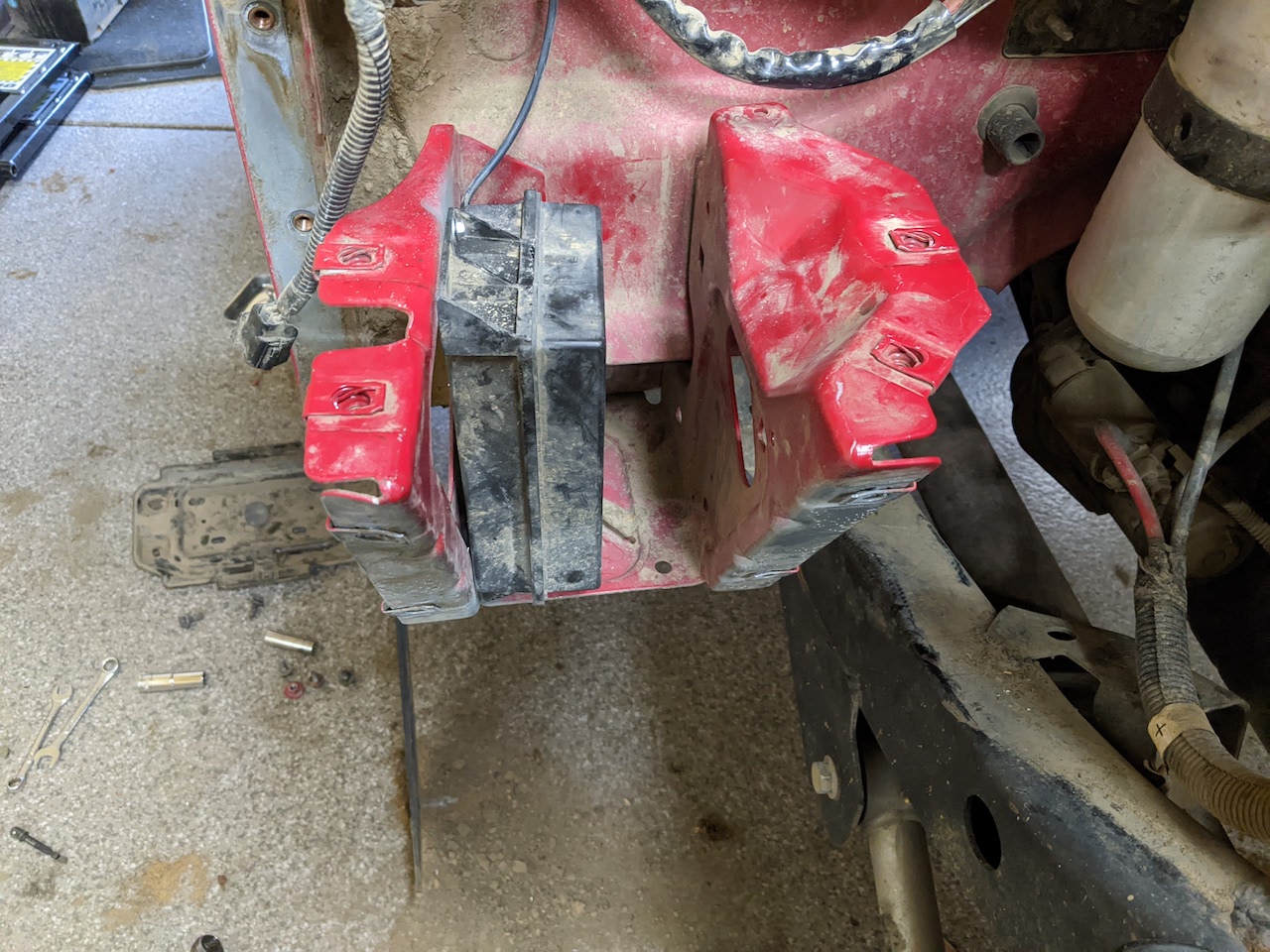
The battery tray on both sides needs to be trimmed just a little to clear the inner fender. The battery mount mostly fits properly, but needs a little force to get it to line up with the holes that are cut in the fender for the bolts. There are no holes pre-drilled in the inner liners for those battery bolts, so I marked them from the back side and drilled them out with the whole thing off the vehicle. The cage nuts on the battery mount were finicky, so I ended up replacing those with M8 serrated flange nuts, which fit better.
The passenger side battery mount has the vacuum reservoir underneath it mounted to the fender. I drilled and mounted it sideways to the battery mount itself to avoid having to mount it to the new inner fender.
Passenger side vacuum reservoir
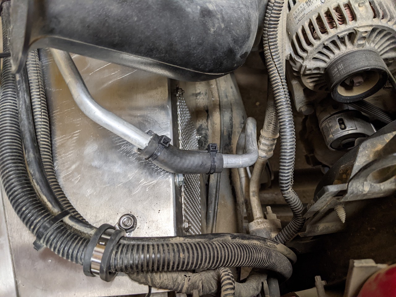
On the passenger side, the AC liquid line is very much in the way of both removing the stock fender and fitting the new inner. I was extremely hesitant to mess with this, but there was no other way. Very gentle pressure with rags in hand made enough room to clear the old fender for removal, and then bending it down to meet the new fender after the fact. Once I did, I zip-tied some fuel hose around the line to give it some protection from rubbing on the corner of the fender.
Passenger side A/C line with hose bushing
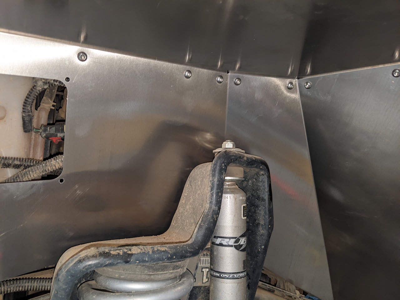
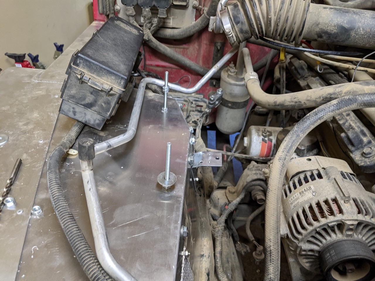
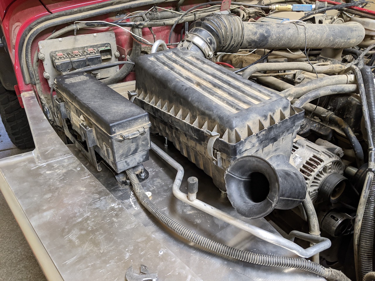
The stock air box does not have a flat bottom, so it does not easily mount to the new fender. I ended up mounting it on long 1/4-20 bolts coming up through the inner fender using the stock rubber-bushing-ed holes. 1/4-20 nuts on the underside with fender washers provide support and nuts on the inside to keep it in place work well. I used a simple angle bracket on the inside vertical face of the fender for the third bolt. This works and lets me angle the air box just enough to clear the hood (just barely) when closed. I had to remove the passenger side radiator support rod to do this, but with the new sturdy fenders, that thing was definitely just for show.
Studs and bracket for the factory air box
The factory fuse box bracket is easy to bend to fit the new fender and bolt into place with the factory bolts (and some M6 lock nuts).
Factory air box and fuse box mounted
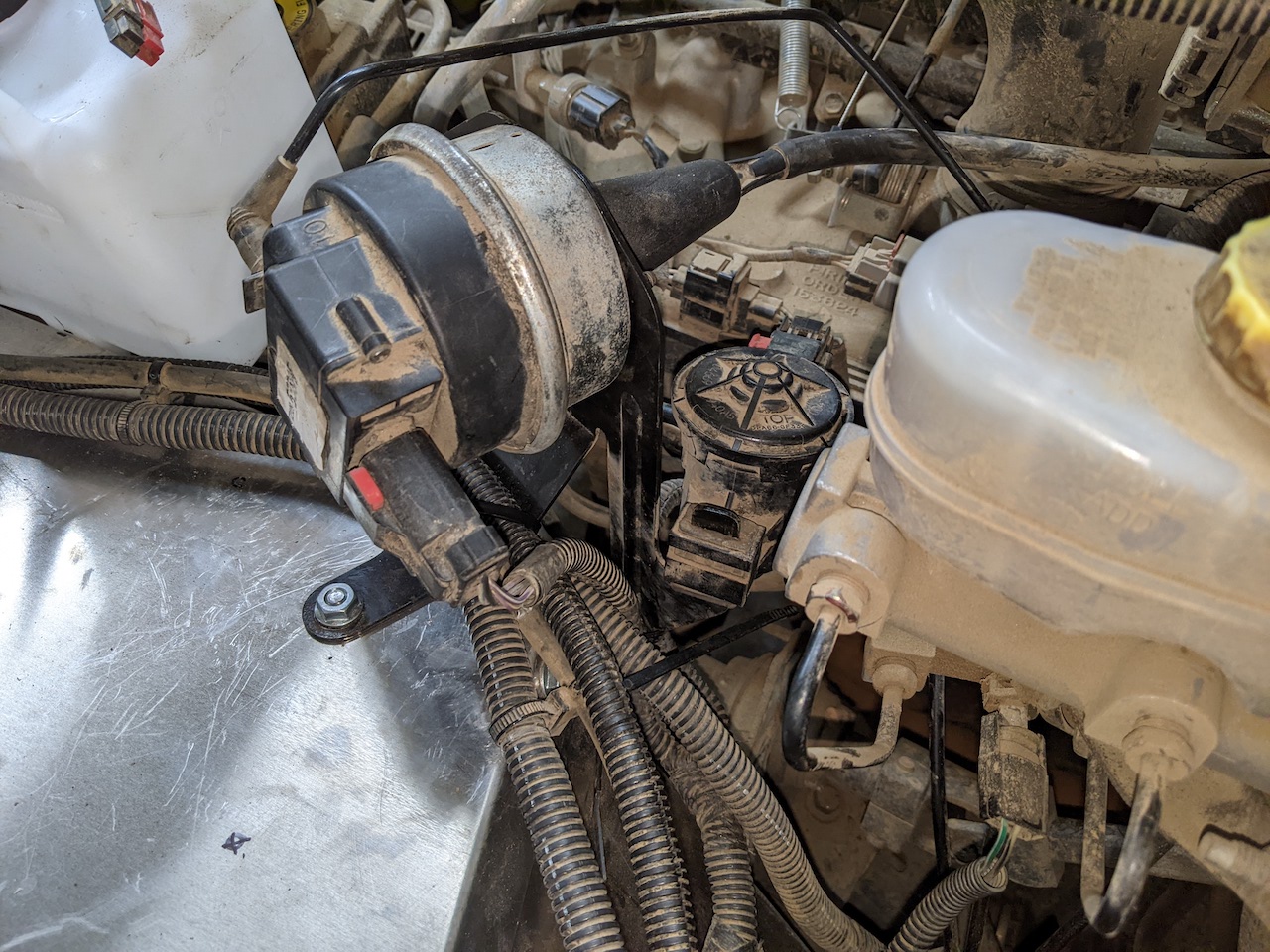
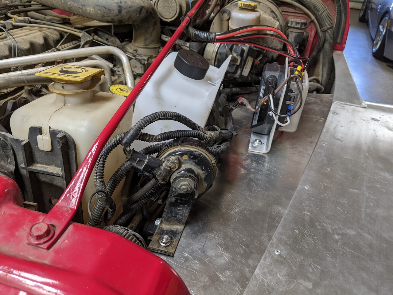
On the driver side, I had the cruise servo, horn, washer bottle, and an auxiliary fuse box to remount. The cruise servo again was just a matter of bending the stock bracket until all three tabs could be located on the fender and bolted in. The horn is a single bolt and similarly easy.
Cruise servo remounted on driver side
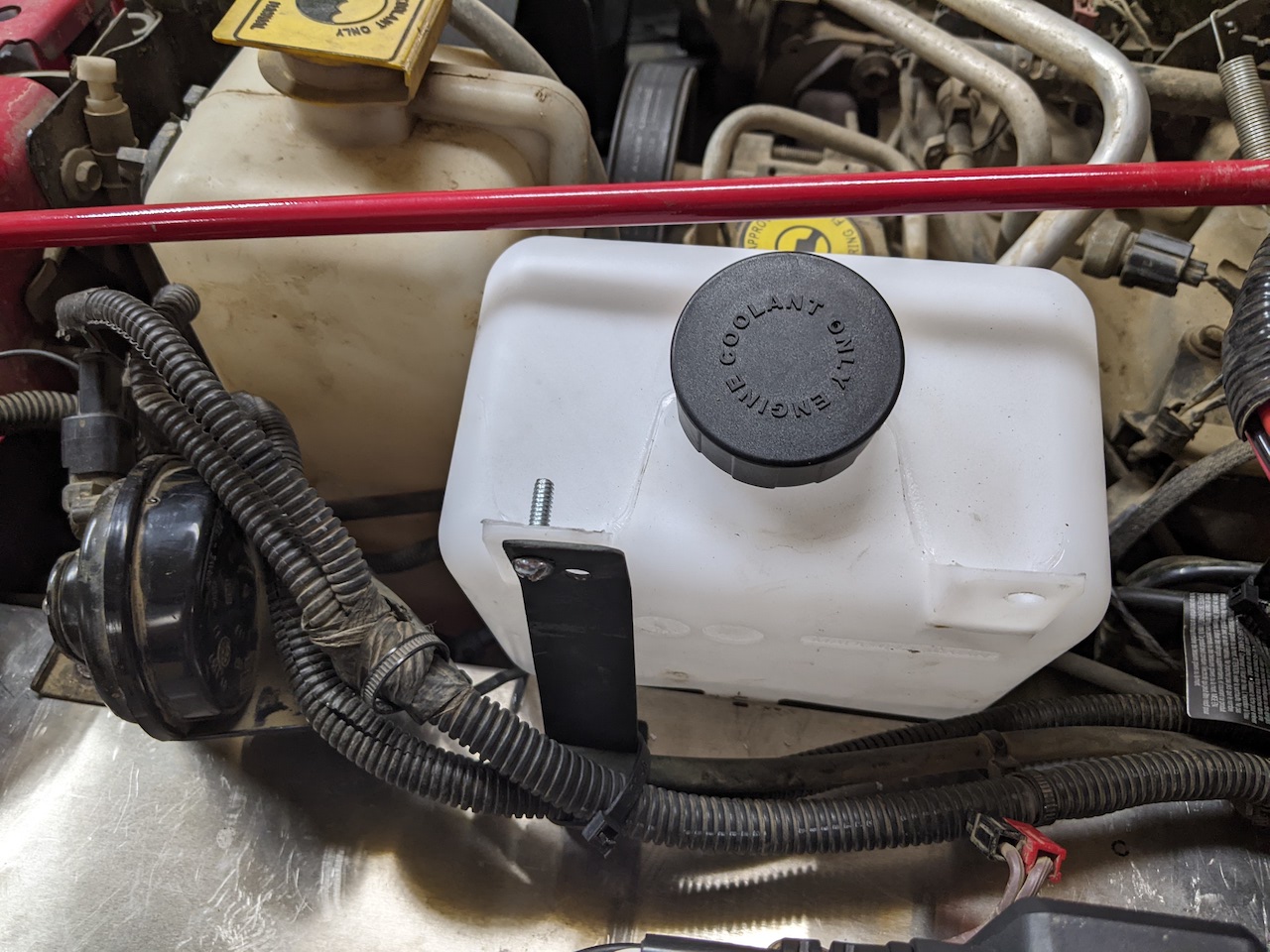
The washer bottle was a little less easy. Mounting it underneath the brake master cylinder would be a good option for most people, but I had already relocated my axle locker pumps there. I used a Dorman 603-001 reservoir bottle, which was a decent size and just fit when mounted on top of the fender at a slight angle. I made a cheesy bracket to hold it in place and it’s fine. The two washer pumps (for the windshield and back glass) can be drilled into the bottom in opposing orientations and I haven’t seen any leaks.
New washer fluid reservoir and bracket
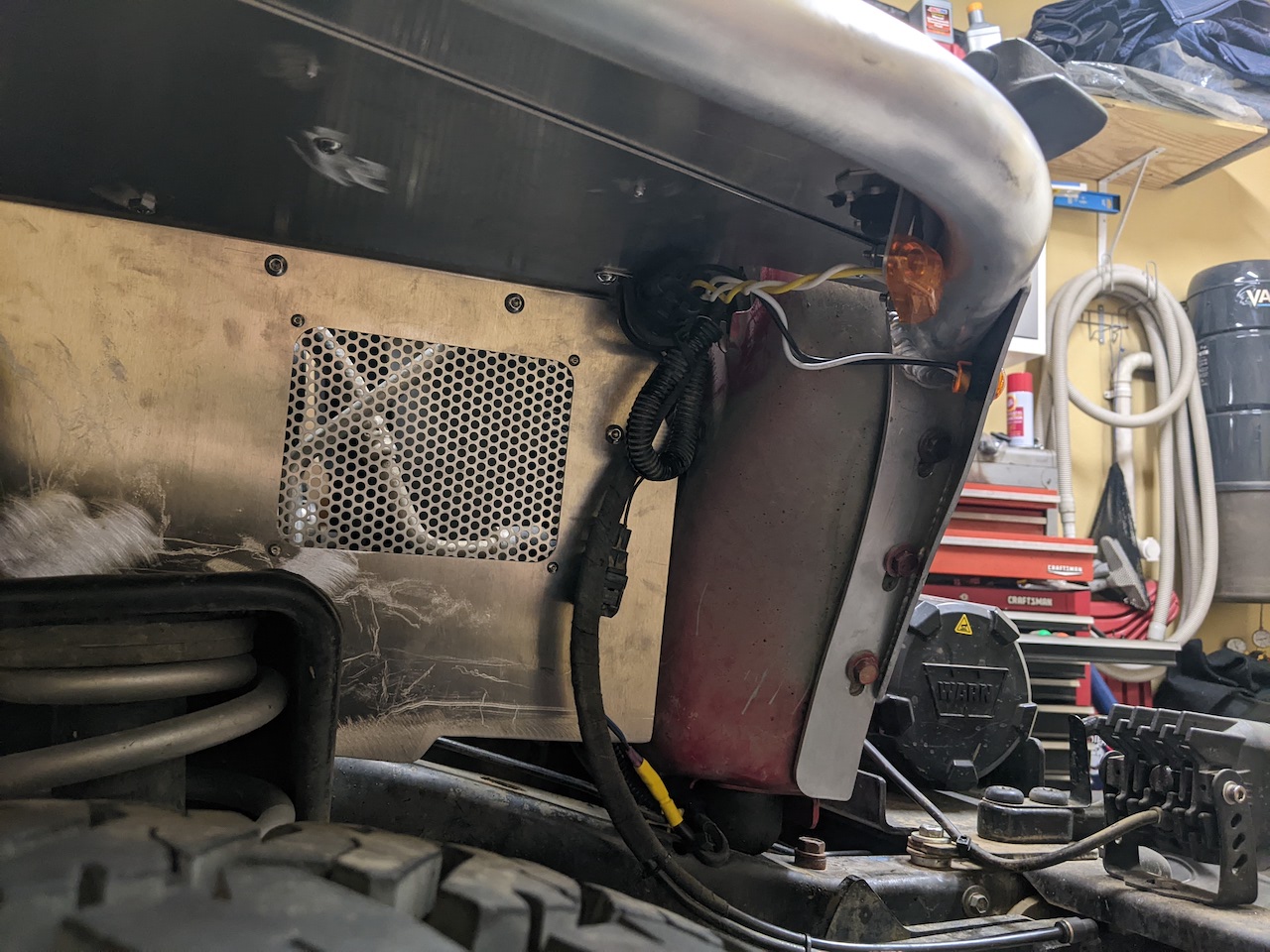
I made a simple bracket for my auxiliary fuse block to keep it upright as I expect water will be streaming in past the fenders now and didn’t want it to sit in the fuse contacts long-term. The horn is a single-bolt indexed bracket which required no modification to bolt to the fender:
Horn mounted
I got the replacement LED light package from GenRight as well. I opted to avoid the diode-and-resistor arrangement to replicate the incandescent side marker behavior and simply wire up dedicated turn signals and side markers. I used three-pin WeatherPack connectors on both sides so I can separate them if I need to remove the fenders later. The wiring and these connectors are tucked up under the top corner of the fender and secured with a rubber-lined cable clamp bolted to the fender. I re-used the factory fog light plug with the “christmas tree” stuck in one of the holes in the inner fender.
Passenger side fog, turn signal, marker lights (air hose is for the SwayLoc)
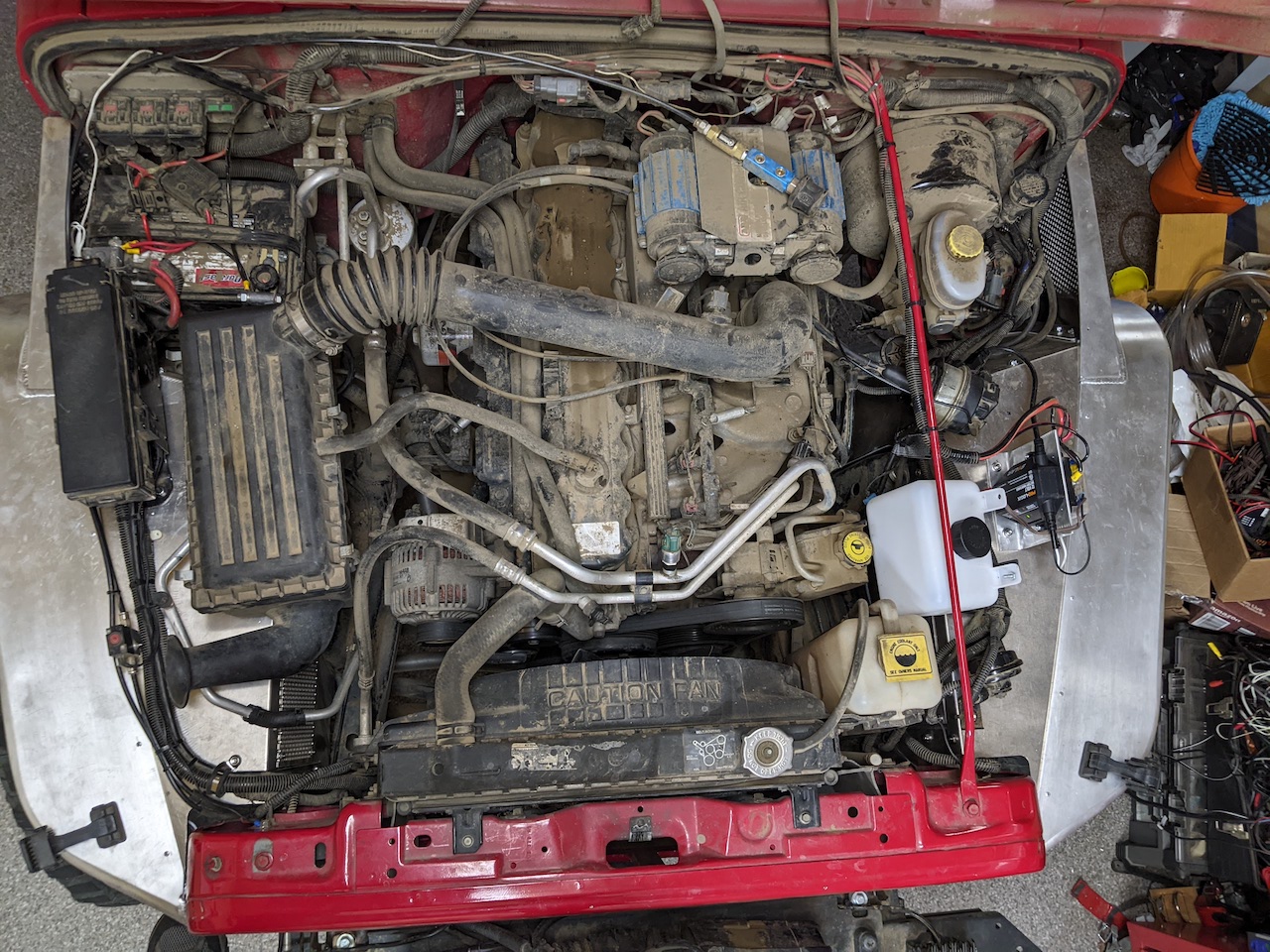
Most of the above was summed up in the instructions with a succinct “simply bolt all the underhood stuff to the new fenders” statement. A bit misleading.
All finished
So in the end, I think everything went fine. Way more work than I was expecting, but not more than I was willing. I wish the instructions were available on the product website, I wish they matched the actual product, and I wish they said even as much as “you will have to custom mount everything under the hood, so beware.” I get that this is a little more like “pieces of fenders that can be assembled to a finished product” but I’d at least like to know ahead of time that nothing is pre-drilled and is a little more of a “choose your own adventure” … adventure.
Recently my Icom IC-7000 died during transmit. The result was a totally-dead appearance, which I resolved as detailed in this recent post. After repairing it with new parts, the radio powers on, but all is not well.
The radio now exhibits a strange symptom related to the Po (power output) and ALC meters. In SSB mode, pressing the mic key shows about half-scale deflection of the power meter with no modulation and regardless of the RF Power setting. This should be zero. With modulation, some meter activity over the static level could be seen, but never full deflection. Further, in FM or RTTY mode, the power meter would show about 80% deflection when RF Power was set to 100%. This should show full-scale. Lastly, in SSB mode the ALC meter would show full deflection with no modulation if the RF Power was set over about 40%, and zero if it was set under that level. ALC should mirror the modulation input, regardless of power.
At first, this seemed reminiscent of the self-oscillation problem that could occur in the 756 and 746 radios, where the RX line wasn’t fully pulled to ground during transmit, causing similar behavior with power deflection during transmit with no modulation. However, I ruled this out by looking at the current draw on the power supply. In SSB mode with no modulation, the radio would only pull an additional two amps or so, despite the meter showing about 50W output. The power draw would fluctuate as expected with voice peaks, even though the power meter did not show any activity. In FM or RTTY mode, the power supply would show about 22A draw even though the radio claimed it was putting out less than 80% power.
Another very interesting manifestation was that the radio wouldn’t drive an external tuner. Even when connected to a dummy load, the radio would kick off a tune cycle, the tuner would achieve a satisfactory result, but the radio would kick the TUNE indicator off after it was done. My guess was that the confusing power output indications to the CPU yielded a “not a good match” determination by the radio itself.
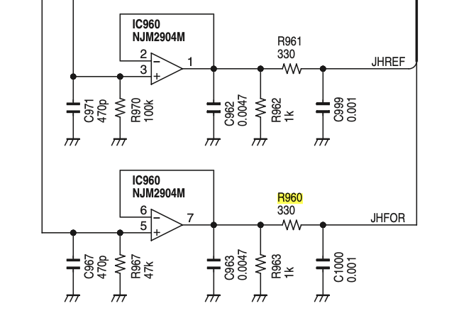
All of this led me to think that something in the power metering or ALC circuits was not right. The forward and reflected power is sampled on the PA board at the antenna connector and fed to IC960 where it is amplified and fed to the CPU on the main unit via the HFOR and HREF lines. Since the radio was showing zero SWR deflection, and since the ALC and Power meters were based on the HFOR line, I focused there.
There is a check point in the ALC signal on the main board – CP1601. I measured 1.7VDC here during transmit regardless of modulation input or the RF Power setting. This, to me, seemed to be the problem: basically a static invalid feedback signal to the CPU, which it interpreted as power output when there was none in SSB mode, and potentially less than full output in FM or RTTY mode, when there was plenty.
There are a number of capacitors and resistors around IC960 before the HFOR line leaves for the main board, which I tried to test in-circuit. However, I couldn’t get anything like reasonable values for these without taking them out.
But, there’s a 300 ohm resistor in the HFOR line, R960. I tested this in-circuit and it seemed like a dead short. To further test it, I disconnected the ribbon cables going to the main board, which should free up one side of it and measured again. Still a dead short. So, I pulled it out and replaced it with as close of a temporary resistor as I had locally: 200 ohm. To my delight, the radio started behaving normally! SSB with no modulation showed no power deflection, and modulation made it bounce as expected. RTTY and FM showed full-scale at 100% and otherwise mirrored the RF Power setting as I backed it down, as expected
After this change, I measure differing voltages at CP1601 depending on drive and power output, which is what I would expect. The radio also happily drives the tuner, and seems to measure the proper SWR when fed with 25 and 100 ohm loads. I expect it is either not achieving full output (or over-driving the PA) due to the wrong-value resistor I installed. After replacing the temporary unit with the proper value I will test power output to make sure it’s behaving properly
I have a bit of a love/hate relationship with my Icom IC-7000. I think that it’s a fantastic radio, with a ton of stuff packed into a very small size. My radio has suffered several failures over its life and has let me down at critical moments. I want to document the most recent failure for posterity, which happens below, but first I’ll cover the background. If you are not interested, skip the history and go straight to where I describe the latest failure and my analysis.
Background
In my early SOTA days, I was hauling it up to mountain peaks with me and operating in all kinds of conditions. I’ve also used it at home, for field day, and in the back country for heavy digital modes like Pactor-3 during events, most of the time with less-than-ideal makeshift antennas. It has definitely seen a lot of action, and has lived life far from the safe environment of an indoor ham shack’s desk top. I think that it packs an incredible amount of functionality and performance into a very small package, and it was definitely a front-runner in that category. That may be why it seems to have a somewhat poor reputation for being prone to failure. I don’t really fault the radio for punching above its weight class, or Icom for pushing the envelope. Like a specialty sports car, you buy it for the performance, not the reliability. In reality, if this thing died, I don’t really know what I’d replace it with; there’s really no equivalent offering today, in my opinion.
The first major issue happened while I was using it in the backcountry to provide Winlink messaging for an event, about 2012 or so. Occasionally, the radio would just go “deaf” on HF for several minutes at a time. It would be sitting there in receive mode showing background band noise (or actual signals) and then suddenly show a zero S-meter and no noise (other than internal receiver noise) for several minutes. This would persist across all bands. Then as suddenly as it went away, the receiver would come back and it would work fine for a while…until it wouldn’t again. For this, it went back to Icom, along with a detailed description of the problem and a video showing the symptoms over the course of several hours and several such events. Unfortunately, the usually-stellar Icom service center let me down on this also. They refused to watch the video and claimed that they were unable to reproduce the problem (I’m guessing because they only tested for a few minutes). They re-seated the ill-fated ribbon cables in the radio, and sent it back to me with a bill for their troubles. They also tried to argue that what I described was my own ignorance and that obviously I had some noise source in the house that was coming and going, despite the problem first manifesting hundreds of miles away, and persisting across all bands simultaneously. But alas. In general Icom service has been great and has a good reputation for being so. Despite my poor experience with one technician, I’m still an Icom fanboy.
When the radio came back from Icom, it went straight on the shelf. They couldn’t reproduce the problem, which means I couldn’t trust it. I was disappointed and frustrated with the service center, so I just moved on. At that point, I was using my Elecraft KX3 for SOTA stuff, which is, perhaps, the perfect radio for it. The IC-7000 stayed on the shelf for probably two years until I decided to get it out to play in a contest. When I tried to power it on, I got the “click-click of death” behavior. The radio wouldn’t power on, and just energized and then de-energized the internal relay when I pushed the power button. I was shocked, because I literally hadn’t powered it back on since Icom returned it to me and it seemed like they sent it back in worse shape. I tracked this down to a shorted tantalum capacitor in the head, which is a semi-well-known failure in these radios. It doesn’t seem like that would have happened while sitting on a shelf without any power for two years, but I’m not sure. I made that repair and the radio came back to life again. I still didn’t trust it, so it went back on the shelf for a couple more years.
This past year, I did field day for the first time in a while and had a blast. I wanted to use the IC-7000, but didn’t trust it so I used my IC-7200 (which is also a fantastic radio, but not really well-suited for contests). After field day, I decided to get the IC-7000 out and work some HF from home in order to put it through its paces. It held strong for hours of full-power SSB QSOs and I was starting to think that it had been exorcised of its demons. That is, until they popped out again.
The latest failure
At one point while transmitting, the radio shut off and then rebooted. Each time I would transmit, it would shut off, and then it got stuck in some sort of loop. Whenever power was applied to the DC jack, the radio would sit in what seemed like a tight reboot loop of just clicking the relay on and off (it was so fast that the screen never had a chance to come on). I took a break, let the radio sit for a while without power, and when I came back, it powered on and continued to work for some time after that. However, it was short-lived and at one point it shut off while transmitting for what would be the last time. The radio was stone dead, showing no signs of life. No relay clicking, no speaker popping, no significant power draw when plugged in, just … nothing.
Being totally not incentivized to spend more money and frustration with the Icom service center, I decided to take another shot at diagnosing the problem. The shorted capacitor in the head had been self-resolvable, after all. I found some information about the power up process that the radio goes through, which was helpful in catching a lead to the actual fault. At all times when the radio has power, the “logic unit” (i.e. the CPU module) receives the 14v input voltage through the HV line. This powers a 3.3v regulator on the logic unit itself, which powers the CPU. There is a pull-up resistor that brings the PWRK line high to the 3.3v rail from the regulator, which goes to the control head. To power the radio on, the control head brings the PWRK line to ground, which the CPU notices, and powers on the rest of the radio by energizing the main relay through a driver transistor.
Checking the PWRK signal on the head connector (pin 2), I saw that it was at about 2.0v, well below the expected 3.3v. Pulling the cover off of the logic unit, I checked the regulator and found that not only was the output low (about 2.4v right at the regulator), but the input was also about 2.7v instead of the expected 14v from the supply.
My thought was that, like the previous capacitor failure in the head, I was looking for something that is now shorted to ground, either on the high or low side of the regulator. Checking a bunch of the bypass caps on both sides, I found none that seemed to be problematic, so I thought maybe the regulator itself was faulty. I removed it (in pieces, unfortunately) and as soon as I did, the input pad was reading 14v from the supply again.
I thought I was in good shape, so I temporarily soldered a TO-220 3.3v regulator I had in my stash to see if that would solve the problem. Unfortunately, it did the exact same thing, showing the same low input and output voltages.
Still on the path of expecting something was dragging either the input or output to ground, I decided to try to isolate the logic unit from the main unit, to see whether the fault was on one or the other. I powered the logic module while disconnected from the main unit by feeding the regulator’s input directly. Sure enough, the output held at the expected 3.3v, with no voltage drop on the input side. This, I figured, meant something on the main unit was shorted. I put the logic unit back into the main unit, and again fed the logic regulator directly, expecting to see the output be pulled down. However, even seated in the main unit, the regulator behaved properly: no voltage sag on either the input or output.
At this point, I took a break, assuming the fault was in one of the main ICs, like perhaps the CPU itself and that I’d be looking at a more substantial replacement of that entire module, or worse. But, then I had the thought that if we’re really dragging the 14v from the supply down to ~3v, we would have to be pulling a lot of current through something and things should be smoking (and they weren’t). Further, the PWRK line was available on the outside of the radio, which means it really needed to be protected from over-current if something contacted the exposed pins while power was applied.
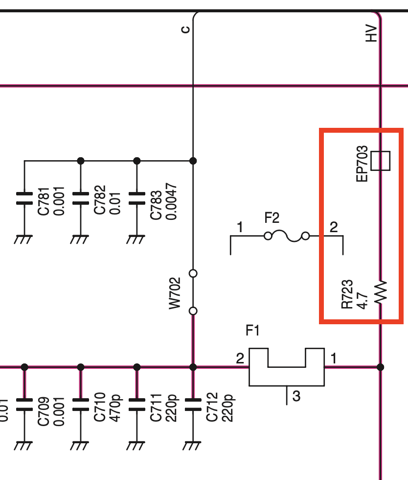
So, I started tracing the HV line to its source. The logic unit gets it from the main unit, which basically passes it straight through from the PA unit, which is where the DC supply connects to the radio. Here, the HV line is fed from the DC supply through the c line of Bus Line 1, through an RF choke (EP703) and a 4.7 ohm resistor (R723).
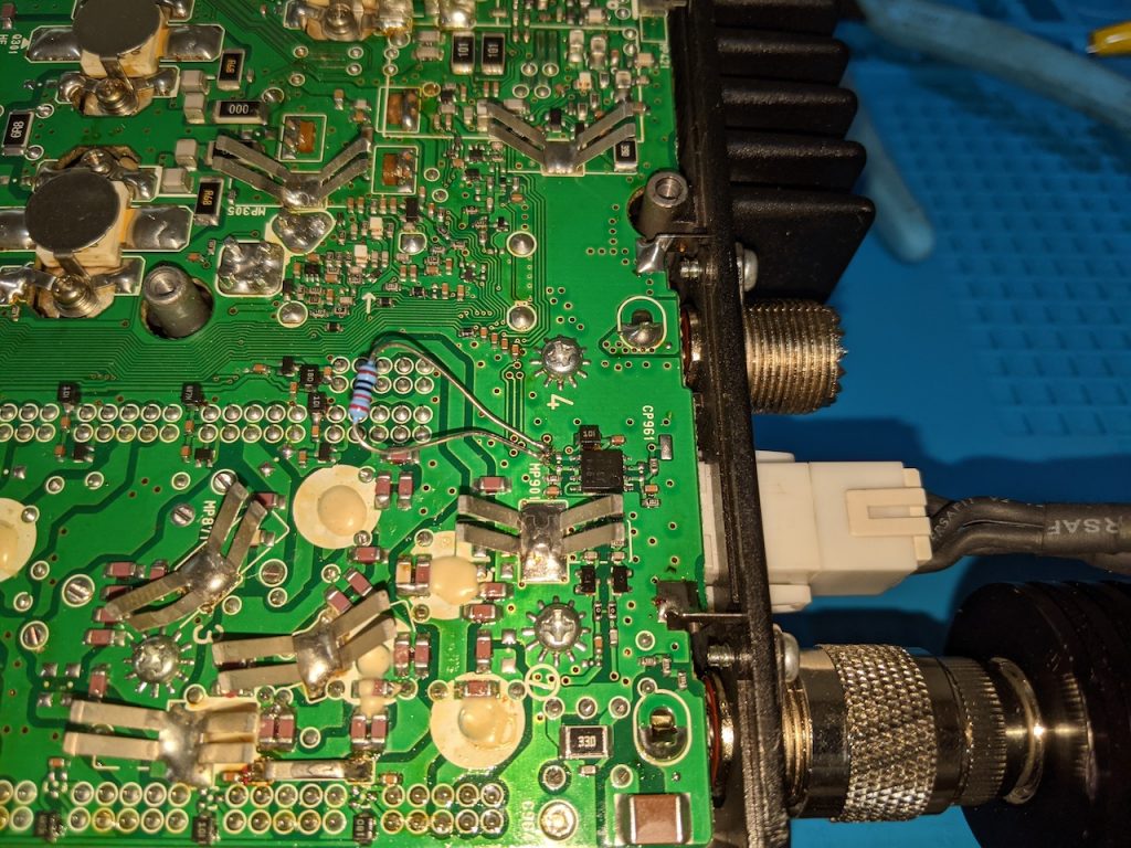
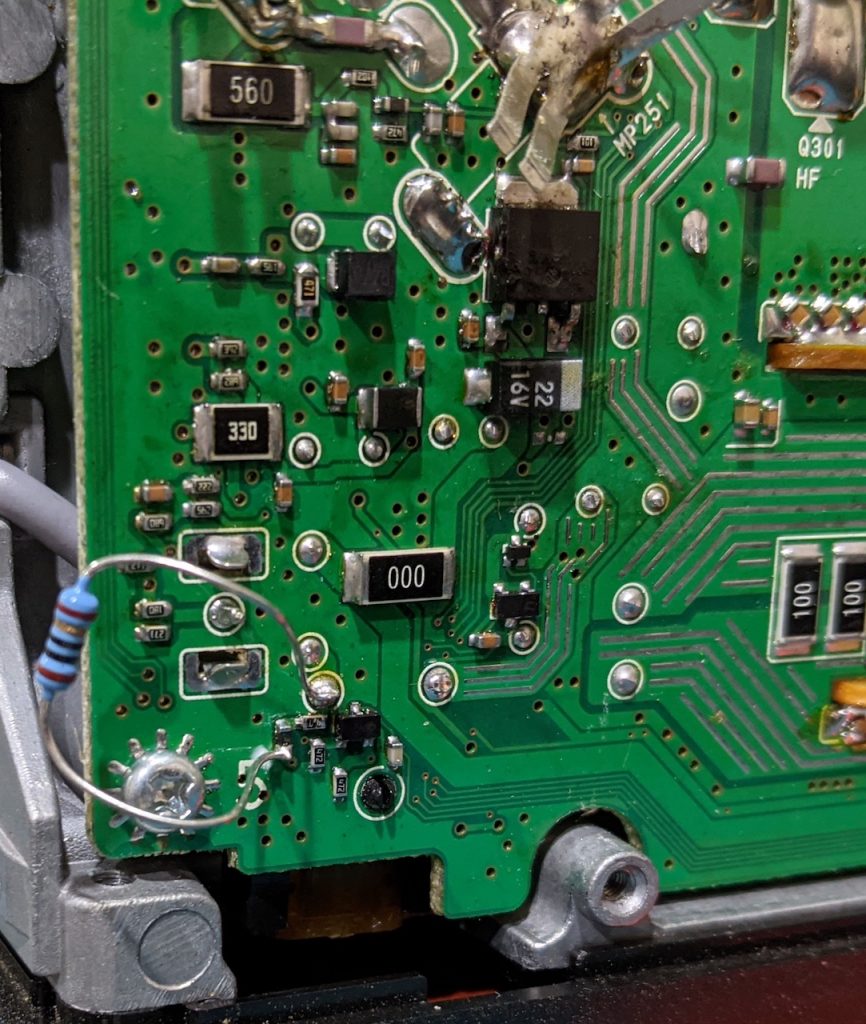
This, I assume, is the current-limiting resistor to prevent that always-on HV line from smoking a trace if it contacts ground. So, I found those two components on the PA board to measure them, and luckily found them on the bottom (exposed) surface by the front-loading fuse holder. The choke read zero ohms as expected, but R723 measured (in-circuit) at 52 ohms!
The thinking here is that R723 failed and is showing much higher resistance than expected. Under no load (with the logic unit disconnected), of course the HV line reads full voltage. When applied to the regulator and CPU on the logic unit, the input voltage drops too low to start the CPU and thus no response to the power button input. It’s also possible that the CPU is running, but when the power button is pressed, the low voltage and near zero current provided to the relay gives the impression that nothing is happening.
Again looking to actually solve the problem before I make a Digi-Key order, I bypassed R723 with the lowest value resistor I had on hand, which is 10 ohm. Sure enough, the radio responded to the button stimulus and powered right up!
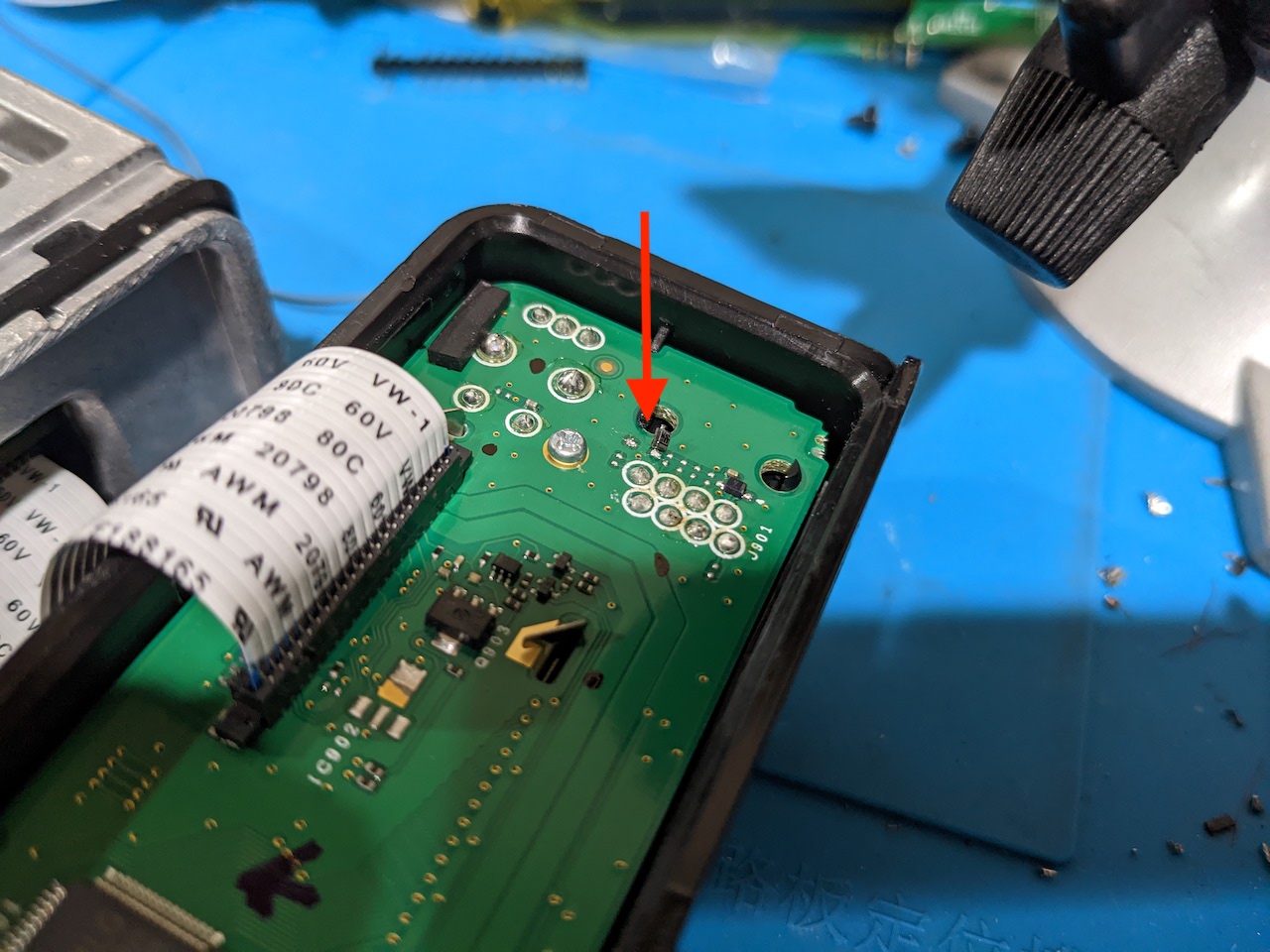
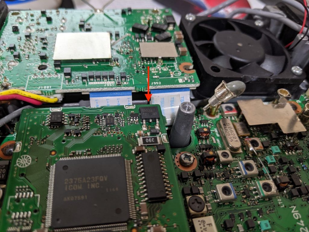
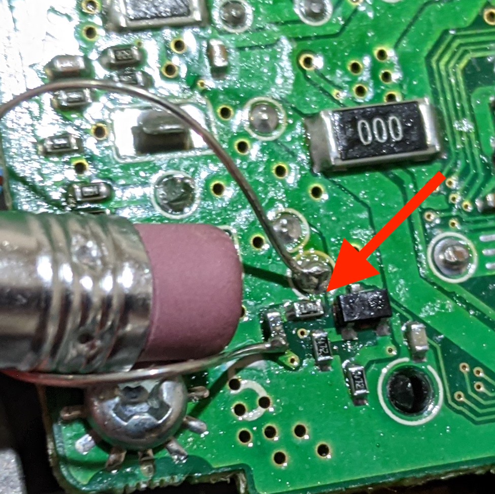
At this point, I think I’ve resolved this latest failure. I’ve got to replace the regulator I removed (in pieces), which will be easy. Far more difficult will be replacing R723, which is smaller than a pin head. Shown here by the red arrow, pencil eraser for scale:
If that doesn’t go well, I may just formalize my bypass resistor in the circuit and call it good. I didn’t find any reports “out there” of this exact problem manifestation, so hopefully this write-up will help someone else if they suffer the same problem, or provide clues for a solution.

 And like the D710, this now allows the use of any off-the-shelf straight-through ethernet cable as a head separation path – much easier to source than the RJ11-to-RJ9 cable that the naked D700 requires.