
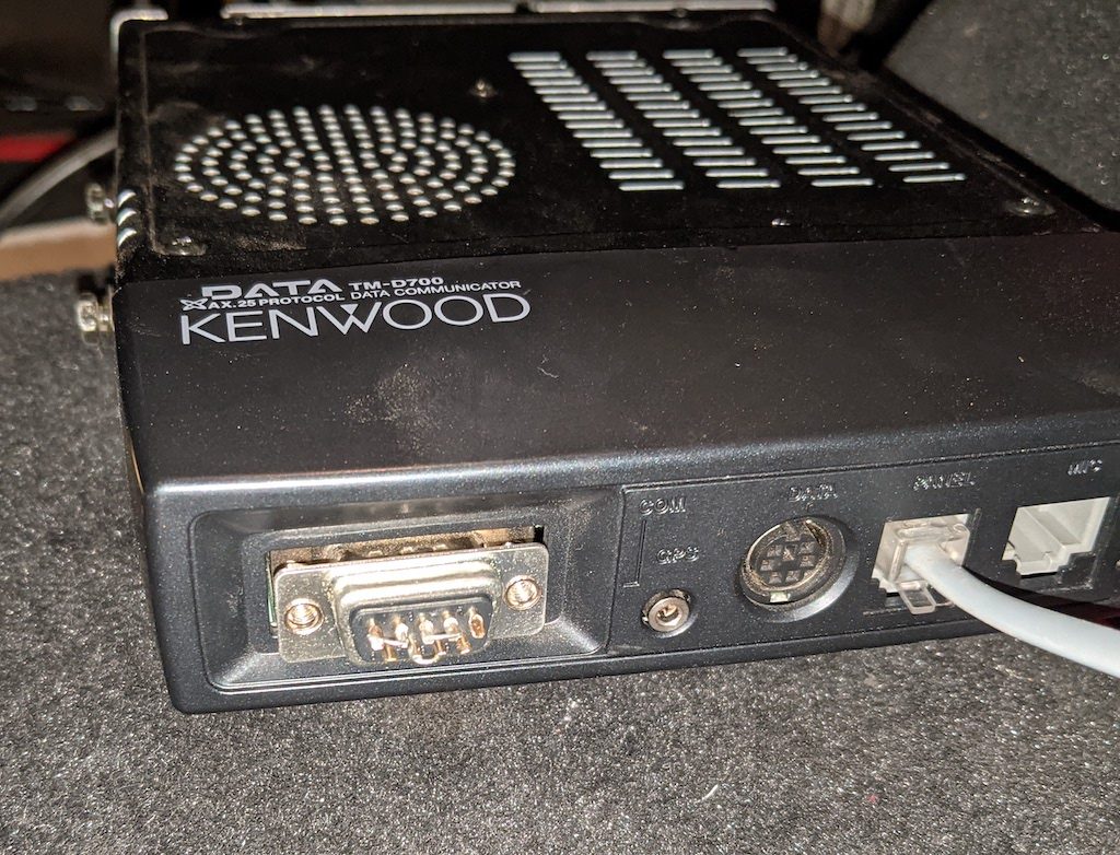
I have a couple of older Kenwood TM-D700 radios that I use for APRS stuff. They’re solid radios, and even have some features not present in the newer siblings, like the TM-D710. But, they don’t have integrated GPS devices, they don’t even support SmartBeaconing, and they were designed long before Bluetooth was common of course.
I recently decided to integrate a Bluetooth serial adapter directly into one, which would make it easier to use things like APRSDroid. With Bluetooth serial, APRSDroid can pretty much replace most of the APRS functionality in the radio, but using the inbuilt TNC for the actual modem part. This means a phone or tablet in range of the radio can enable rich mapping, SmartBeaconing, and messaging, without any cabling to the actual radio itself. Bluetooth-based connection is a feature of the current TH-D74 portable radio and it is extremely convenient.
Unlike the newer TM-D710 mobile, the TNC in the D700 is in the body of the radio itself, and thus that is where the Bluetooth serial module needs to go. Luckily, the front nose of the radio is plastic, and provides a good place for us to put the module so that it won’t be shielded by the rest of the case:
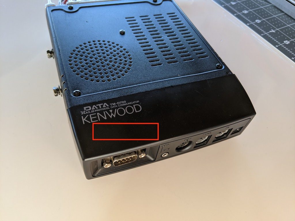
The red box roughly indicates the spot where the module will go. Conveniently there is a little extra space for it under the cover.
The module I used is an HC06, which is available from various places in a lot of different form factors, brands, etc. The only problem is that these modules almost universally work on TTL-style 3.3v serial. The TM-D700 has a proper RS-232 port, which works at differential 12v signalling. Thus a TTL serial converter is required, as well as a voltage divider to lower the 5v output from it to 3.3v for the Bluetooth module. The 3.3v coming from the Bluetooth module is enough to drive the RX side of the TTL level converter without issue.
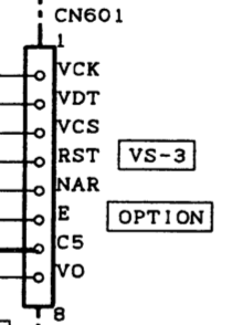
So, for this to work, we’ll need to find a 5v source inside the radio to power the Bluetooth module and the TTL converter. Then we will place the TTL converter between the serial port on the radio and the serial port of the Bluetooth module. Luckily, the radio has an option slot for the VS-3 “Voice Synthesizer” module, and that module requires 5v from the radio. Since I don’t have that module installed in either of my D700s, it seems like a perfect place to grab it, especially since the radio expects to provide some amount of power (at 5v) to that module. The pins are super tiny, but you can probe them to see which one has the 5v. It’s the second one from the edge closest to the side of the radio. Pin 7 on the schematic, labeled “C5” for “Common 5v”:
There is also a ground at the other end of the blank spot for the module, which should be easy to spot. If you have a VS-3 already installed, you may need to find 5v and ground elsewhere. I grabbed mine from this area and tacked down the wires with a little hot snot to keep them from moving.
I chose a super small TTL converter, but which already had a female DE-9 connector. I removed that connector and just wired between the appropriate pins so it would fit inside the radio.
Now, the easy thing to do here is to just wire the TTL converter to pins 2, 3, and 5 on the board, as they would be if you were connecting externally to the port on the radio. However, this will present two problems. First, you won’t be able to use the serial port externally anymore to do things like program the radio or use the TNC for other purposes. Second, you won’t have any way to access the Bluetooth module’s serial port if you want to do things like change the PIN and human-readable name. However, there’s a good solution for this: hijack some of the unused pins. The schematic shows that several of the DE-9 pins are not connected (NC):
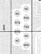
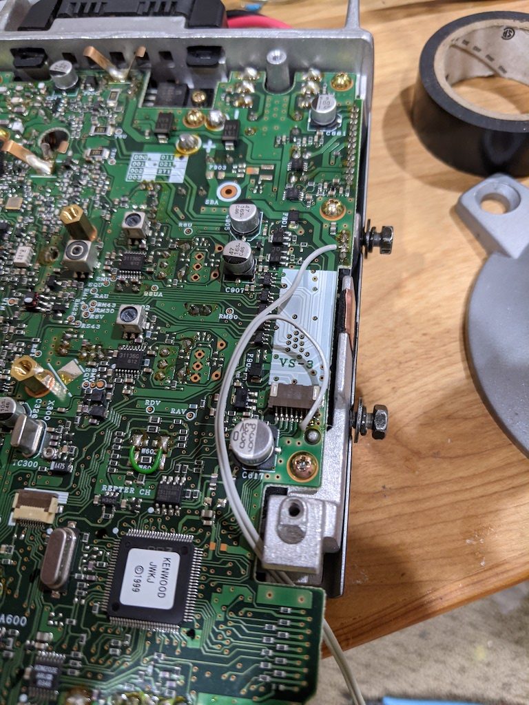
Pins 2 and 3 are the ones we eventually need to get to, and luckily pins 1 and 4 are not connected and right next to the ones we want. So, if we connect to 1 and 4, we can then use a super small loopback “dongle” in the form of a DE-9 female plug with pins 1 and 2 connected, and pins 3 and 4 connected. So, when we want Bluetooth to be operational, we can leave the plug inserted into the front of the radio to loop it through to the serial port; when we want to program the radio with a computer or use the TNC directly, we can remove it. If we need to talk directly to the Bluetooth module for programming, we can make a serial cable that runs to pins 1 and 4 instead of 2 and 3. Further, if we decide we want to have the Bluetooth module connected to the GPS connector (for read-only “Kenwood waypoint mode” operation), we can make a small cable to run from the GPS port to pins 1 and 4 of the DE-9. We can keep the connection to pin 5 (ground) all the time, so no need to account for that. Here’s what that looks like (prior to flux cleanup):
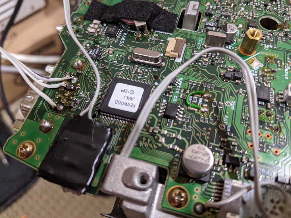
You can see the TTL converter wrapped and hot-snotted into place on the board just below the connector. There is a relatively blank spot on the board here with just some SMT buffer resistors that make a good spot for it.
Otherwise, locating the Bluetooth module is all that is required. On the top side where the TNC module and ribbon cable is located, there is room to place the module under the cover. It probably isn’t necessary to affix it, but a small dab of glue will hold it, antenna side up, in place relatively easily:
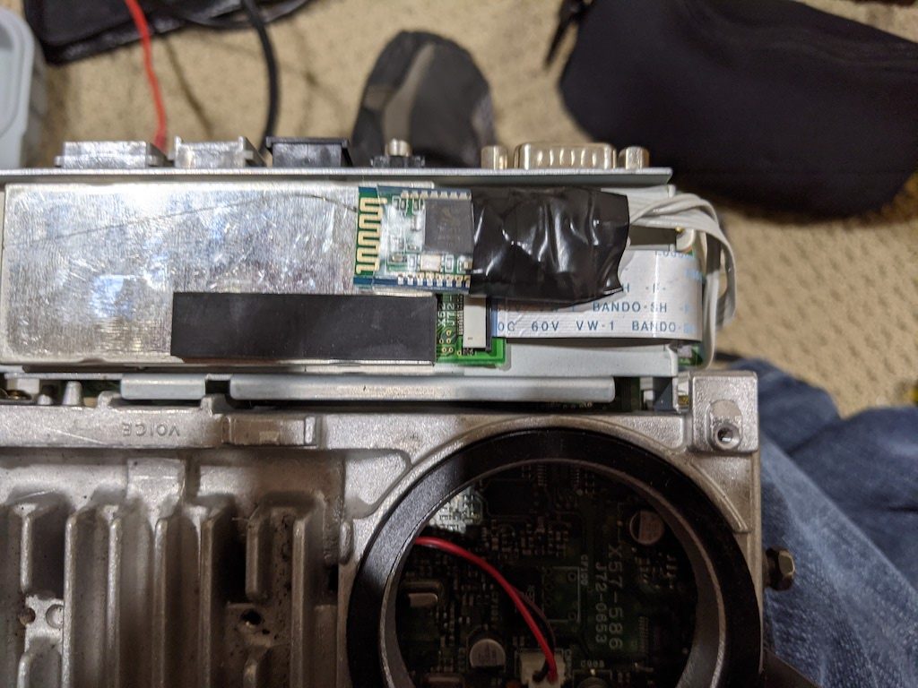
It’s not critical to wrap the connection side like I did since the cover that goes over this is plastic, but it helps to secure the wires, the voltage divider resistors, and the bottom of the board in case it comes loose.
After the radio is re-assembled, it’s time to build the loopback. Just a single female DE-9 is all you need for this. Here’s what it looks like (before covering it for safety):
Note that the D700 requires hardware flow control to be working. Since the Bluetooth module doesn’t use (or provide) this, just jumper RTS and CTS (pins 7-CTS and 8-RTS) together to tell the radio it is always “clear to send”.
The GPS connector is right next to it, so a very short connection between pins 1, 4, and 5 on the DE-9 to the GPS connector would enable waypoint mode instead of native TNC mode.
Technically, this is all you have to do to make it work. However, you probably want to change the PIN from the default (which is 1234), as well as change the name to something useful (like “TM-D700” or similar). You need to make up a serial cable, as described, that connects to pins 1 and 4 (instead of 2 and 3 by default). Once you do, you can configure a serial terminal for 9600,8n1 and type the following two commands:
AT+PIN9876
AT+NAMETM-D70
Note that the module doesn’t seem to use carriage returns or line feeds to note the end of a command (as it should), but instead, the inter-character delay timeout. So, the best thing to do is type those commands (one at a time) into something else, and then copy/paste them into the serial terminal so that they show up all at once.
And with that, you should be good to go. The Bluetooth module will turn on and off with the radio, so power it on, and pair your Android device. Then configure APRSDroid for Bluetooth, select the proper Bluetooth pairing, choose KISS mode, and enter the following TNC initialization string for the Kenwood:
KISS ON
RESTART
Then when you click “Start Tracking” APRSDroid should configure the TNC to go into KISS mode and you should see some positive response (if verbose logging is enabled). Try sending a position and confirm that the radio transmits to verify proper operation.
Awsome write-up! Stumbled across this looking for other ideas on how to get APRS running again on my D-700. I see the Mobiliink’s too, but those seem like it’s another component to worry about. This integrated solution seems much better and I like that it’s more “old school” Ham than just new plug and play stuff
I may need to catch up with you by email as to some of the pinouts between the ttl and the bluetooth as I’m not 100% sure I understand that, but once I have the parts and the schematics it may make more sense.
73!
Kevin