
I have a couple of Kenwood TM-D700 radios that I like. They are really solid, and for the most part, very good for their integrated APRS capabilities. In the old days when you had to connect a GPS to the radio to get it to beacon, I actually preferred the D700 because the GPS connected to the radio itself, instead of the head like the D710. I always thought that was a really unfortunate design point of the later radio – having to route another cable to the head. When the D710GA came out, that became moot of course, as building the GPS into the head unit itself made it mostly a non-issue.
There are a couple other drawbacks to the D700, like lack of smart beaconing and some annoying rules that require you to run APRS on the left side of the radio in order to tune anything on the right side. But aside from that, they’re nice. I have made a couple of attempts to modernize my D700s in the last, like by hiding a bluetooth serial module in the radio itself. That’s neat and handy, but only useful for a few circumstances.
Recently I had an idea to also integrate a GPS module into the plastic nose as well. I did cram one in there, but it’s becoming a mess (with the bluetooth module as well) and the size of GPS antenna I was able to get in there left me with really sub-par performance. That, and a lot of people mount the radio body in a trunk or under a seat, which makes a receiver in the radio itself less than ideal.
After doing all that work and being underwhelmed, I thought: what if I were to integrate a GPS module in the head unit and plumb it back through to the radio? Putting the GPS receiver in the head was a very nice benefit of the D710GA, since most people have the head up front, usually in view of multiple windows, etc. Doing something similar for the D700 would be nice.
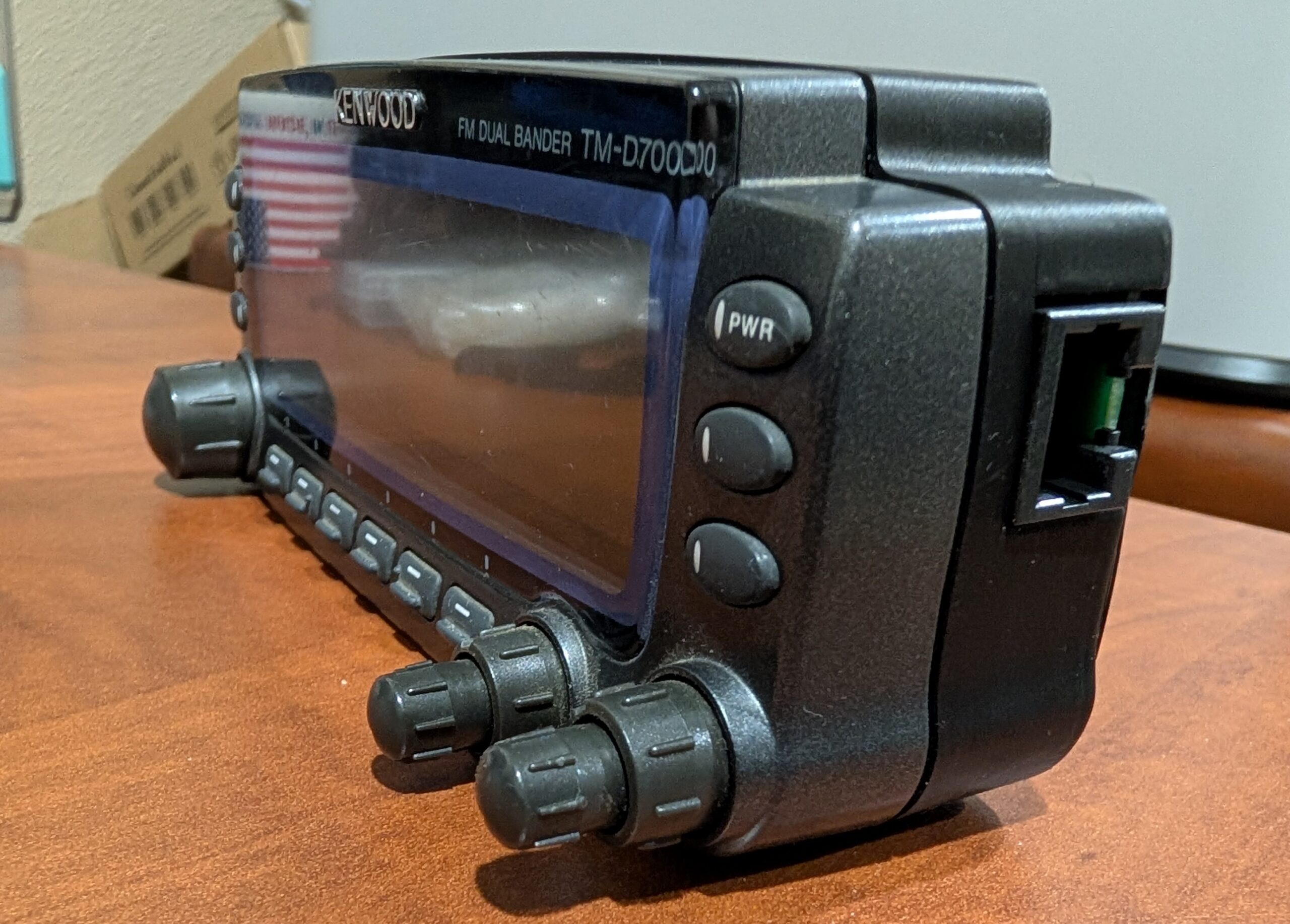
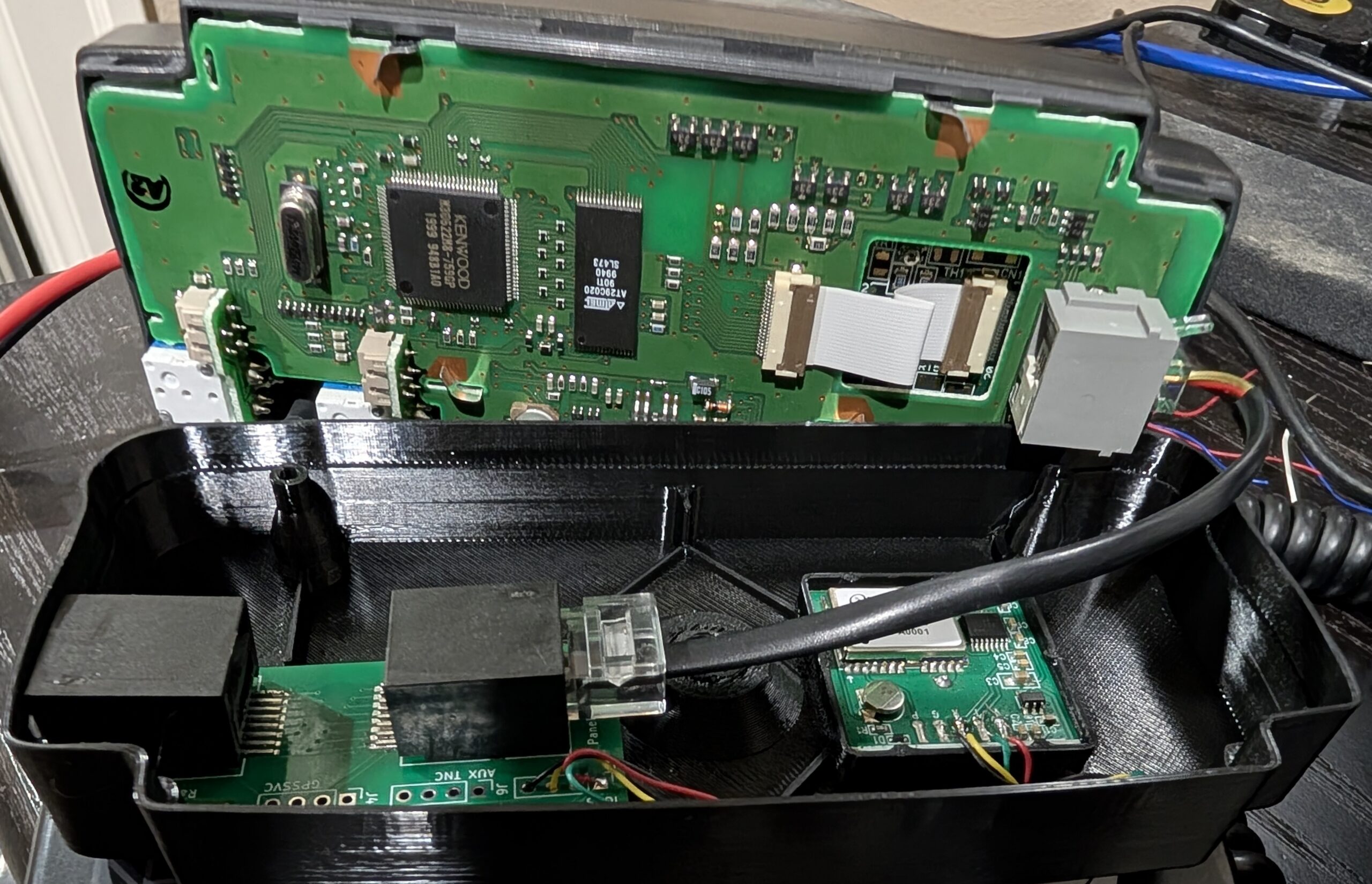
So, I present to you…the D700GA conversion kit. This is a replacement back cover for the control head that houses a GPS receiver and an interface board. The interface board squashes the four usual pins of the control head interface into an 8P8C modular plug (like the D710 uses), along with GPS data lines. Then, another board on the other end of a standard ethernet cable splits the two back out into the RJ11 head cable and 2.5mm GPS data cable. The replacement back cover hides a jumper to the 4P4C original head connector on the left and presents the 8P8C on the right, fully contained within.
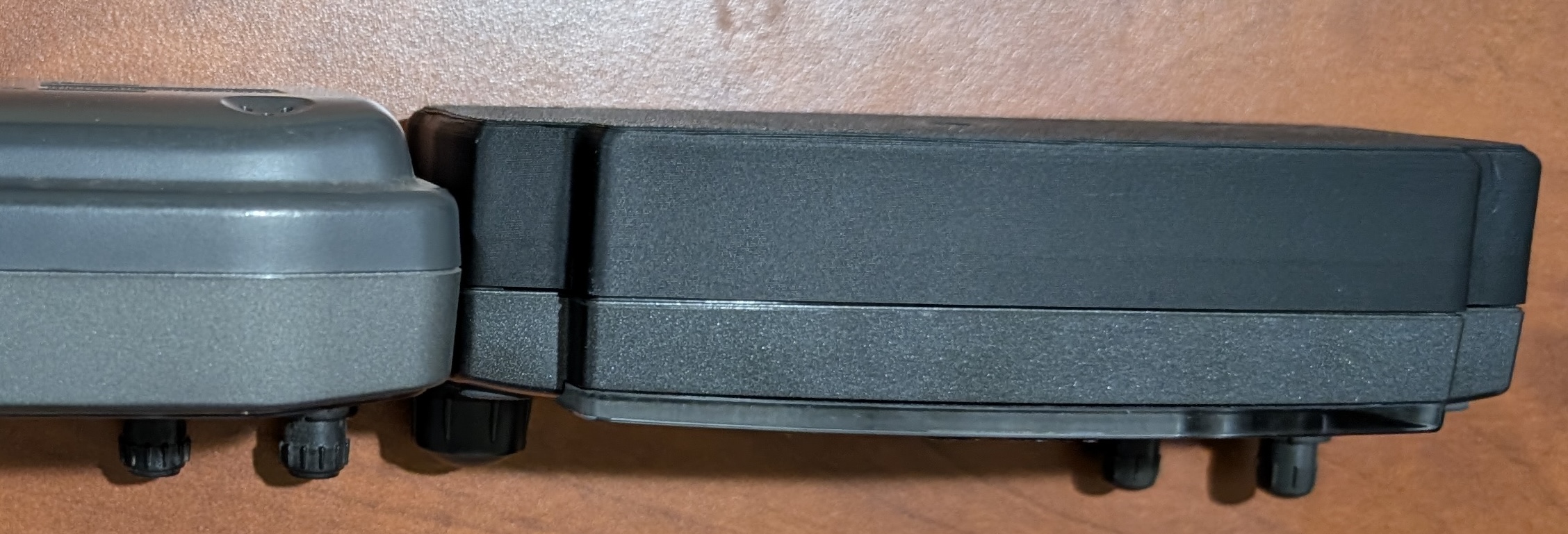
The result is a D700A radio that behaves like a D710GA – you just turn it on, it has GPS and can beacon. The new cover makes the head significantly thicker, but it’s actually similar to the thickness of a D710.
The GPS has a much larger antenna than the one in the D710GA and can maintain a much better fix in suboptimal conditions. It also receives GLONASS and GALILEO in addition to GPS for better performance. Instead of replicating the weird slot mount of the original head, I just integrated 1/4-20 hardware into the back cover for easy interfacing with many other mounting solutions.
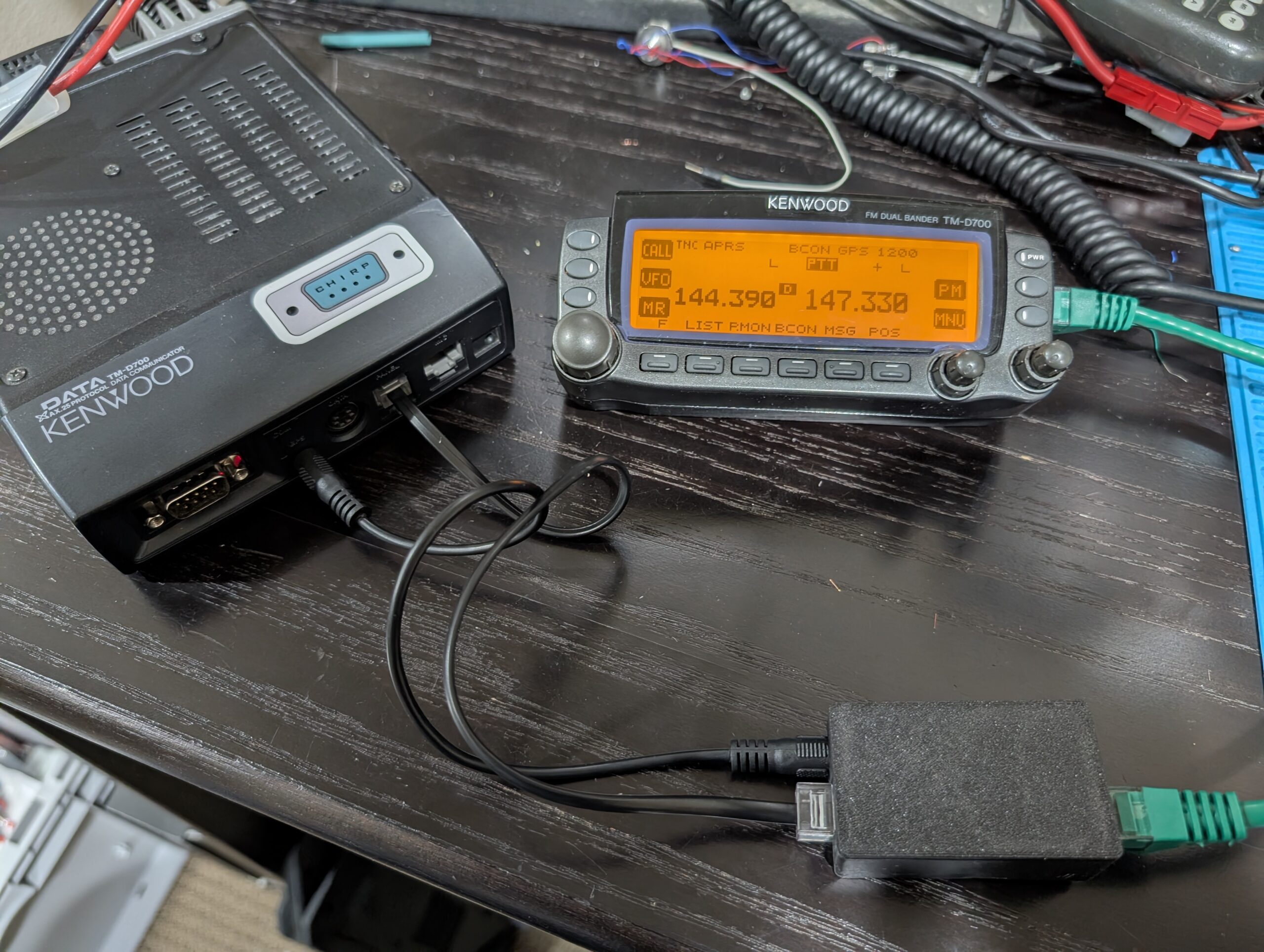 And like the D710, this now allows the use of any off-the-shelf straight-through ethernet cable as a head separation path – much easier to source than the RJ11-to-RJ9 cable that the naked D700 requires.
Very very very good job….what gps module did you ise? Is there a chance of providing the full step by step procedure or full and closer photos of the pins? 73’s de SV4KIO
More info here")
Dan,
This is fantastic! I’m in the process of building out the radio setup in a brand new vehicle and this would be a great mod to do to my D700. Are you willing to share the 3D model and parts list you used in this build?
Thanks and 73,
Mark
Hi Dan,
Are you planning to sell these kits?
Scott -NØLNE
Yep, available here: https://www.tindie.com/products/40955/ although the ones I had available got snatched up. Should have more soon")
Great project! I’m curious about the power supply for the GPS module and the interface board in the head unit: since you’re now consolidating everything over a single ethernet cable, did you run into any issues with voltage drop or noise interference on the GPS data lines, especially when using longer ‘off-the-shelf’ ethernet cables?
Yeah, before doing this I checked how the radio powers the head. There is an LM05 and LM08 in the body, which I assumed powered the head, but they’re used for things like the mic. The head is powered by a set of push-pull power transistors on the board, rated for 1A continuous, 2A pulse. This is protected by a 1.8A fuse. There seems to be a whole lot of margin here, I assume both “because Kenwood” but also because the head is known to be able to run through a very long cable.
The only indication of voltage problems has been if I’m running the display head dimmed and a 50ft “thin” ethernet cable. I can tell the backlighting of the display is affected by the cycles in the GPS, but it still works fine. At full brightness I don’t notice.
As far as noise on the data lines, the GPS is 9600 baud RS232 (as in, real differential +/-12v) which can go a hundred feet easy so definitely no problem there.