
There is no shortage of writeups online about converting a B7’s ugly yellow daytime running lights to LEDs. It was Nick’s that made me decide to do the actual conversion, and part of the reason why I decided to add yet-another-writeup to the internet’s large collection of them. Most seem to ignore a couple of the important details about doing this, namely how and where to mount the resistors safely, as well as the proper sizing and power dissipation calculations required to select them.
As some background, modern fancy cars monitor the circuit of each safety-related light bulb so that it can indicate to the driver when one burns out. It does this by making sure that, when activated, the bulb draws a reasonable amount of current, commensurate with a properly-sized and working incandescent bulb. When you replace such a bulb with an LED, it draws so little power compared to the original that the circuit monitor thinks the bulb is burned out. Most times, the LED works fine, but the car incessantly warns the driver of the problem.
So, we need to select a resistor to put in parallel with each bulb that will draw (and waste) enough power to fool the monitoring circuit. That will get about as hot as a regular bulb does when it’s on, which means that it’s going to get pretty hot. The original bulb for the DRLs in this car is an 1156, which is a 26 watt bulb. At 15 volts (the maximum you’d expect from your alternator when the car is running), that’s 1.73 amps:
26 watts / 15 volts = 1.73 amps
If we wanted to pick a resistor that would consume 1.73 amps at 15 volts, we’d need an 8.6 ohm resistor:
15 volts / 1.73 amps = 8.6 ohms
Now, they make 8 ohm resistors that are rated at 25 watts, and we could use one. However, that would be running the resistor in the red zone all the time. Also, these wire-wound resistors are only rated at the stamped power when mounted on a substantial metal heatsink (check your datasheet). Assuming you’re not going to mount it on an ideal heatsink, AND assuming you’re going to mount it near a hot high-performance engine, AND expect to drive in the summer, the red zone is not where you want to be.
Even a 50 watt 8 ohm resistor is cutting it too close, in my opinion, given the environment. It’s scary that a lot of people seem to be using 6 ohm 25 watt resistors for this. At 15 volts, that’s almost 38 watts, which is more than the resistor is rated for in ideal conditions:
15 volts / 6 ohms = 2.5 amps x 15 volts = 37.5 watts
This is, in my opinion, not a good idea (sorry Nick!). In my setup, I chose a 15 ohm resistor rated at 50 watts. At 15 volts, we pull exactly 1 amp and dissipate 15 watts:
15 volts / 15 ohms = 1 amp x 15 volts = 15 watts
Since the resistor is rated at 50 watts, this is an 85% margin, which is a lot of safety padding. Pulling 1 amp is enough to fool the circuit monitor in my car.
Given that 15 watts continuous is still plenty of heat to dissipate, I wanted to find places to mount the resistors such that they had adequate air flow, and were physically mounted on something else large and metal to help with dissipation. On the driver’s side, the bracket that holds the coolant tank is just begging to help, with ample free space and pre-existing unused mounting holes:
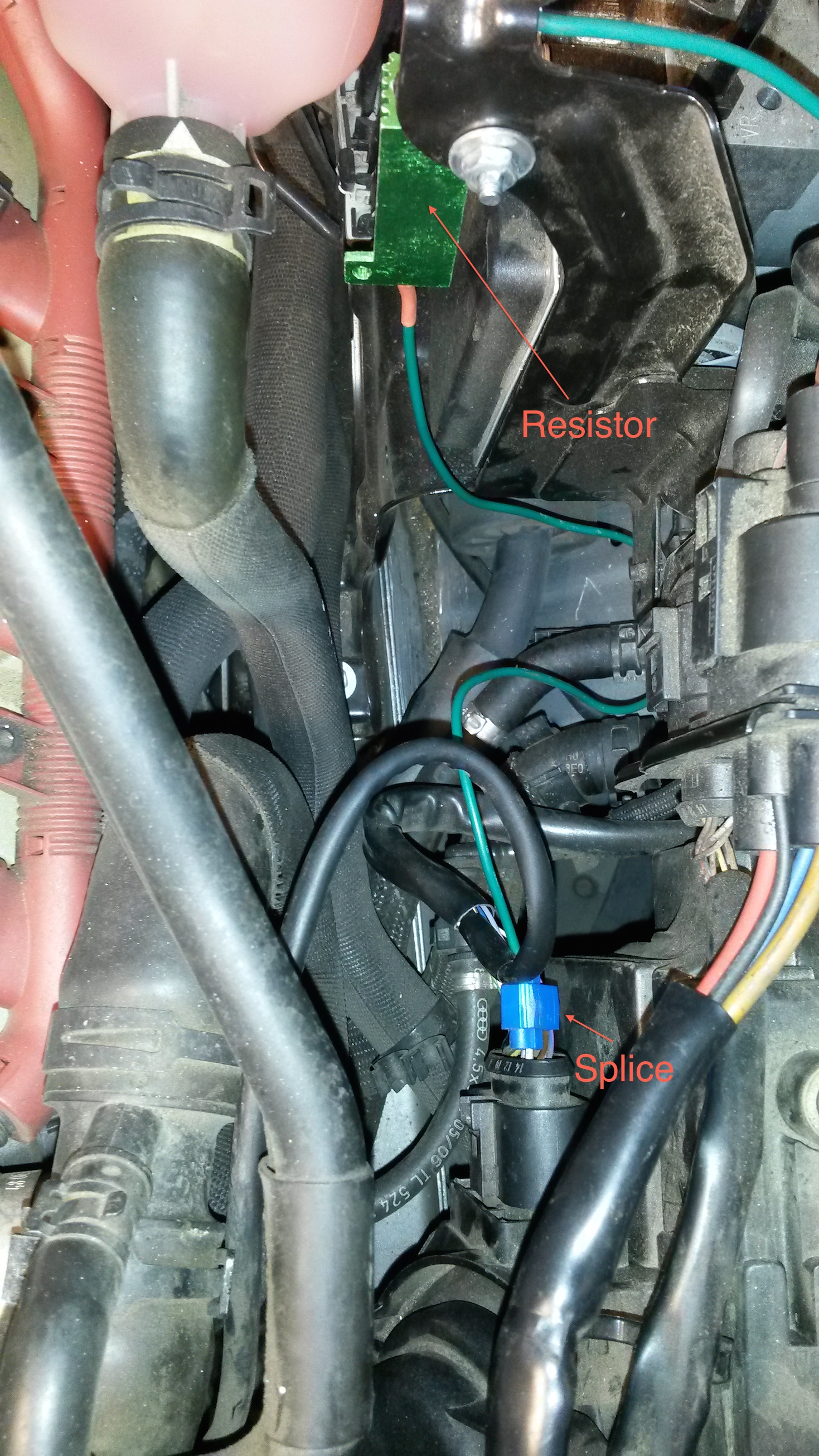
On the passenger side, there are many fewer obvious options. There is a large space under a vented cover in front of the cabin air intake. There is a nice blank spot in the mid-bay separating wall for mounting. I made a small bracket out of some metal strapping, bolted it to the wall, and mounted the resistor on it. The bracket and the wall help to draw some heat away from the resistor.
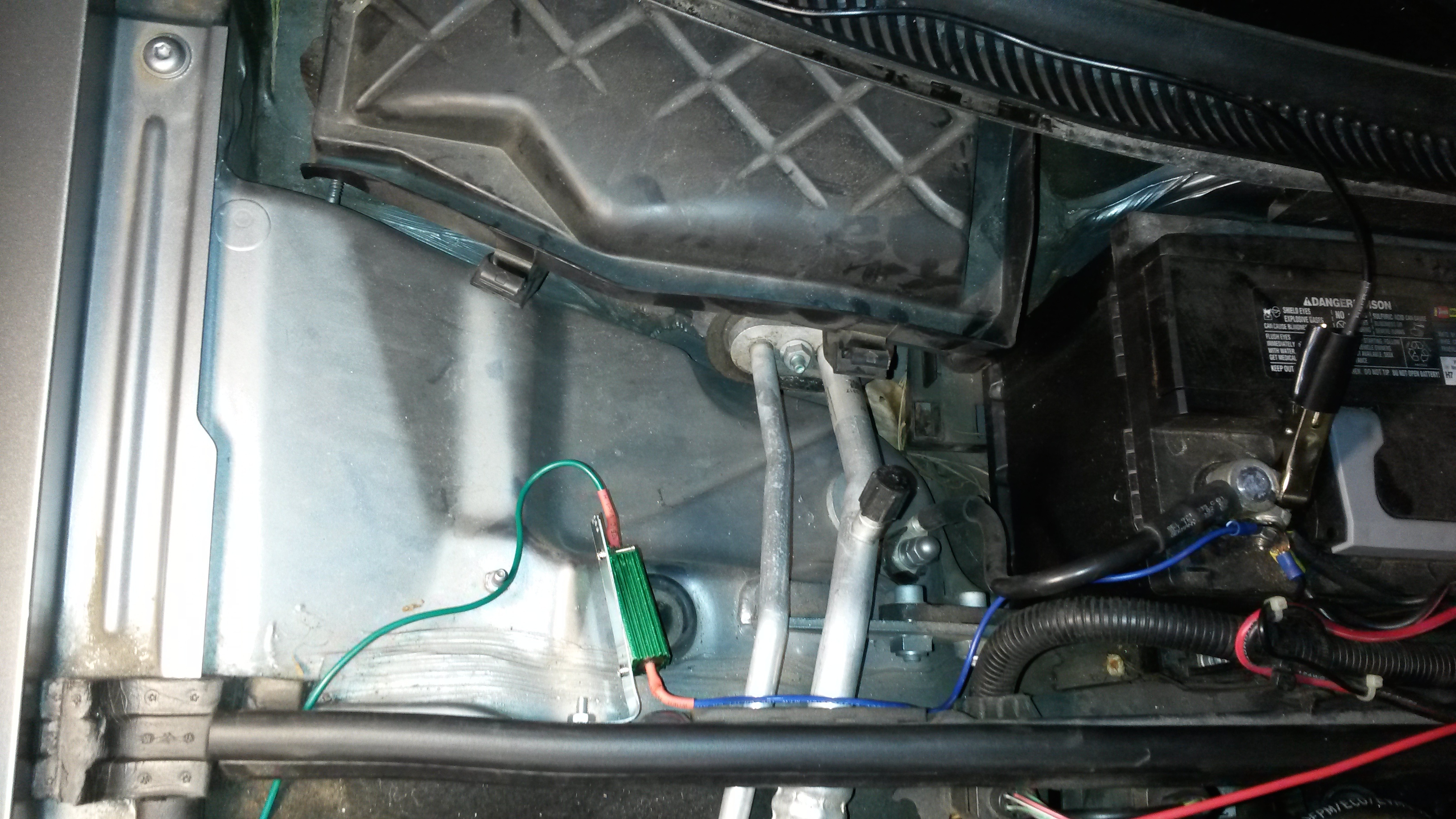
Each resistor needs to be connected to ground on one side and the DRL circuit on the other. The passenger side is an easy trip to the negative terminal on the battery. The driver’s side has an easily-accessed bolt in to the front quarter panel that works nicely.
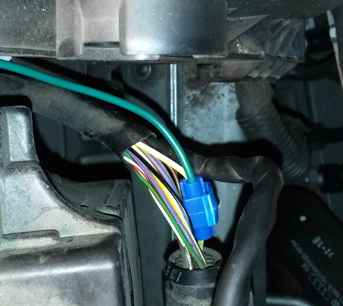
For tapping into the DRL circuit, I didn’t want to pierce the watertight housing of the headlamp assemblies. So, I pulled back a little bit of the rubber cover on the cable that plugs into the housing, found the wire, and used quick splices to tap in. On each side, the wires are labeled on the connector. Wire 12 is what you want.
Even only dissipating 15 watts with a resistor rated at 50 watts, after a couple hours of the lights being on in the garage for testing (hood open, engine not running), the resistors are plenty hot:
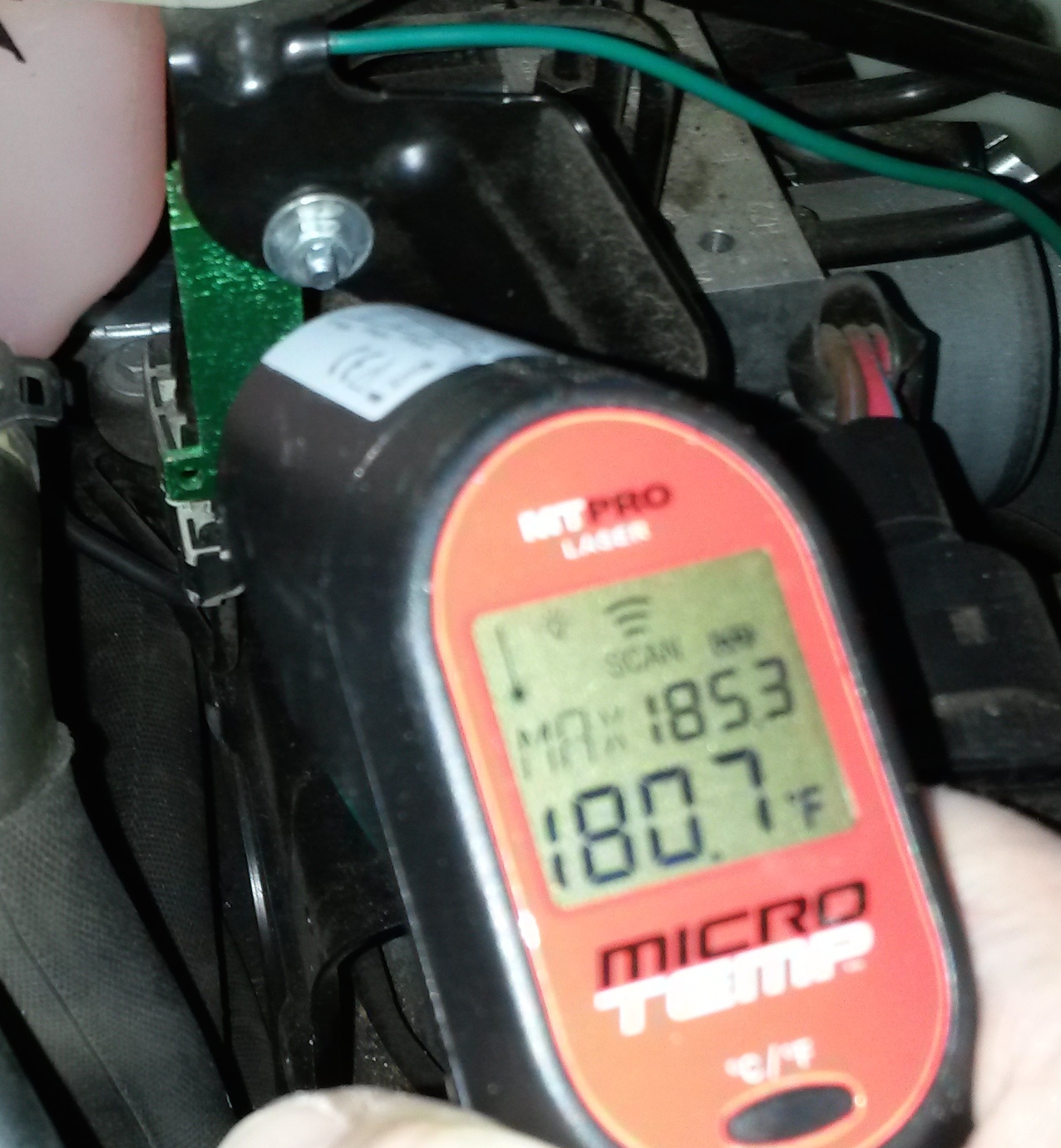
Imagine how hot the 25W 6 ohm resistors that most people use would get!
After the conversion, the car is happy and the daytime running lights look so much better. Just to be clear, this is a 2007 Audi A4 S-Line 3.2 Quattro with the color instrument cluster display.
2 Responses to 2007 Audi A4 LED DRL Conversion
2 Responses in other blogs/articles
[…] which works better on your car, they’re cheap enough it doesn’t hurt. This article on DanPlanet suggests a 15ohm, 50W resistor is ideal, although these are harder to find – I think he has a […]
[…] had this setup for several years without trouble on my S4 (and my A4 before it). This article on DanPlanet suggests a 15ohm, 50W resistor is ideal, although these are harder to find – I think he has a […]